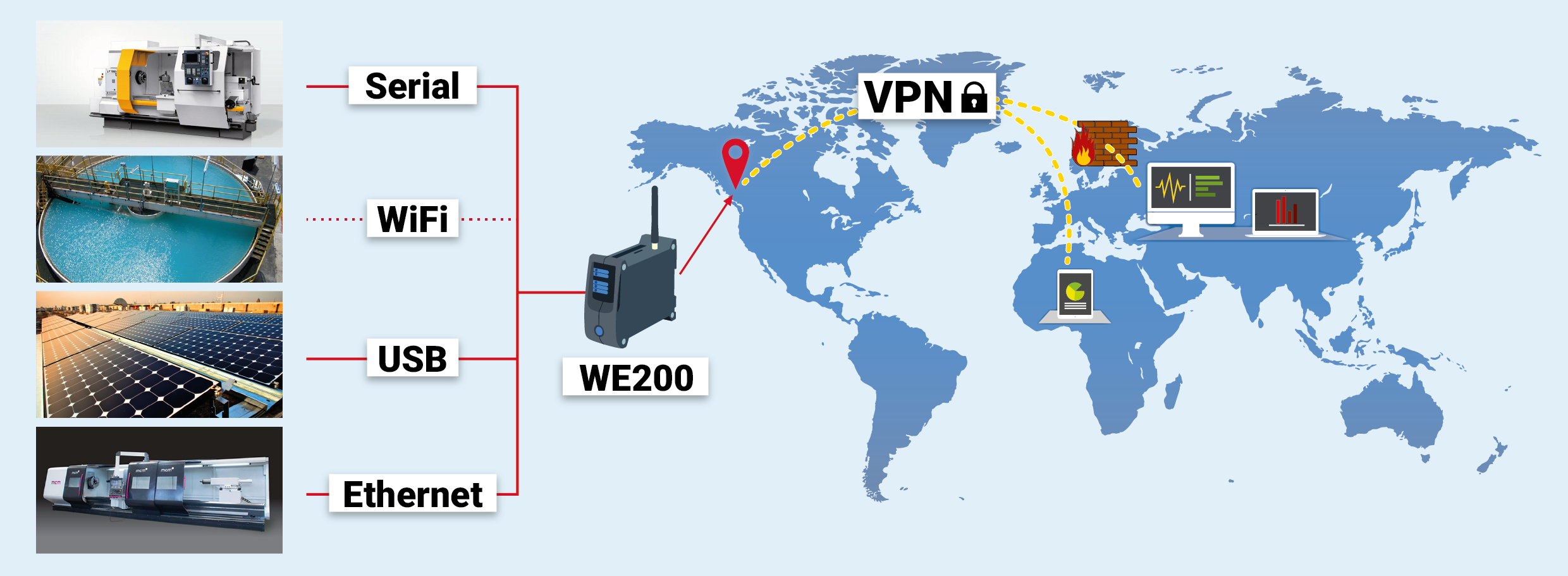
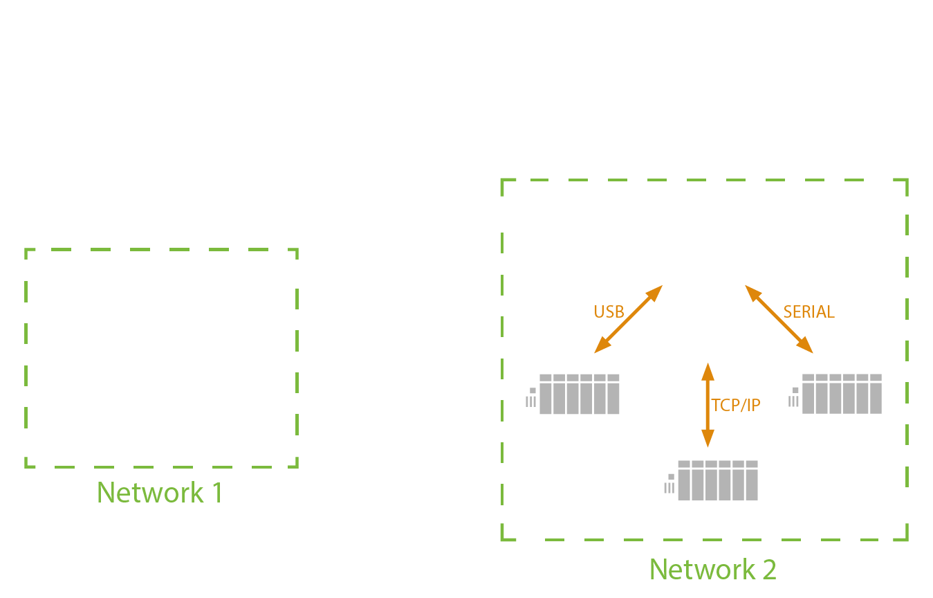
all network interfaces can be activated concurrently.
3.1.1. Data connection and SMS
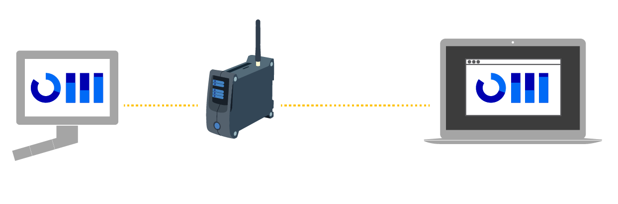
WE200 allows to establish a HSPA/LTE connection (according to the modem required at order confirmation) in order to enter the web interface of the device and send data or emails, even if no Ethernet or Wi-Fi connections are available.
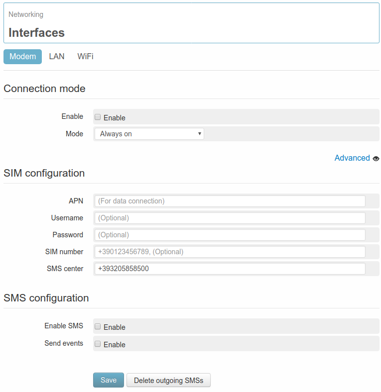
In order to activate the connection enter the page Networking → Interfaces → Modem.
DATA CONNECTION
Once enabled the service with a flag on the field Enable, it’s required to specify whether the connection must be always on or on demand.
- Always on: The WE200 will keep the connection always on. In case it should be interrupted (missing credit, Signal not available..) the connection will be restored as soon as possible.
- On demand: the connection is activated on request by an authorized user through a Wakeup message (7. Commands) and after 15 minutes is automatically disabled. If the activated services require a connection for data sending or email sending.., the connection of the WE200 will automatically be closed at the end of the configured operations.
If the parameters have been properly configured, after a few minutes the HSPA/LTE connection will be activated. On the status panel, positioned on the right side of the web interface, the HSPA/LTE indicator will become green and beneath it the connection uptime and the relevant IP address will be displayed.
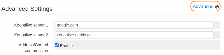
There are some advanced parameters, that can be entered clicking on the option Advanced:
- Keepalive server 1 WE200 checks the connectivity status, trying to reach some preset server at regular intervals. This allows the system to detect any possible critical issue and react promptly to restore the connectivity. If required by the user, the servers used for the keepalive function can be modified
- Keepalive server 2 Allows to configure a second server for the keepalive function, to be used in case the first one cannot be reached
- Address/Control compression It enables/disables the compression of the address/control fields during the negotiation. With exception of particular situations, it’s normally recommended not to change the default settings (enabled)
Make sure that the HSPA/LTE connection has been successfully established, by checking if all necessary operations have been executed:
- Provide the WE200 with an enabled data SIM card (rechargeable or with flat tariff contract)
- Enter the APN (field APN) for the Providers that require it.
- Connect the antenna and check the strength of the available GSM signal.
- Enable the HSPA/LTE service (field Enable).
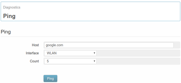
It’s possible to check the quality of the connection by using the diagnostic tool Ping (8.3. Ping).
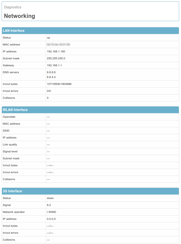
Further information regarding the status of the connection can be found on page Diagnostics → Networking (8.2. Information of connectivity).
For the correct operating of the SMS service and HSPA/LTE connection, it could be necessary to define some SIM’s parameters according to the selected provider.
Those parameters are available on SIM configuration section.
- APN: It’s the name of the access point of the HSPA/LTE network. It changes according to the provider and to the contract with it (in some cases this may be not necessary). It’s an important parameter for a proper functioning of the connection. In case this should not be known, please contact the provider or Nethix Support.
- Username: it’s the username for the HSPA/LTE connection. This field is normally blank, if it’s not differently required by the provider.
- Password: Password to be used for the HSPA/LTE connection. This field is normally blank, if it’s not differently required by the provider.
- SIM number: It’s the Telephone number of the SIM inserted in the WE200. This is not relevant for the functioning (this number is never used by the WE200), but can be used for identifying the device later on.
- SMS center: It’s the SMS Service Centre of the Provider. With some types of SIM this could not be required. If this number is not known, please contact the Provider or Nethix Support.
SMS SERVICE
To enable/disable the SMS service go to SMS configuration section.
Beside the flag for enabling the service, it’s possible to enable or disable the sending of pre-set SMS notifications.
Once enabled the SMS service, it’s possible to test the functioning through the section SMS test: entering a valid telephone number, complete with country code (for example +39NNNNNNNNNN for Italy), the WE200 will try to send an SMS with the following text ” Test message from WE200 “.
For granting the proper functioning of the SMS service, allowing the users to communicate with the WE200 and the WE200 to send alarm notifications, the procedure below must be carefully carried out:
- Enter the SMS Service Centre on field SMS center
- Enable the SMS service on field Enable SMS
- Enable the SMS sending on event (field Send events)
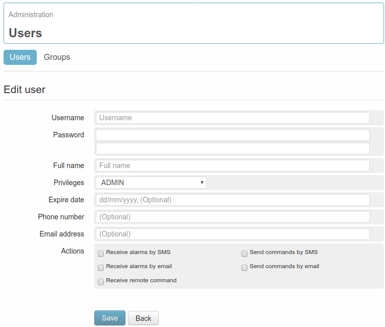
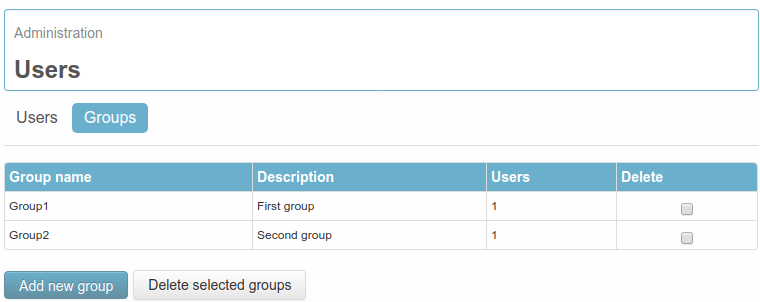
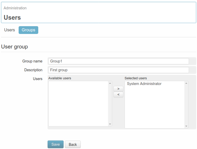
- Define at least one user with activated SMS sending/receiving functions (5. Users)
- Make sure that the SIM is properly inserted and with enough credit.
- Make sure that the antenna is properly connected and that the available signal is strong enough.
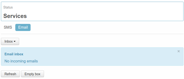
All sent and received SMS can be displayed on page Status → Services → SMS: the first page to be entered will show the SMS received by the device.
In the table the following information will be available:
- Number: shows the Phone number of the SMS sender
- Reception date: displays the date and time when the WE200 has received the message
- Text: contains the text of the received message
The button Refresh can be clicked at any time in order to update all information; Empty box for deleting all messages stored on Inbox.
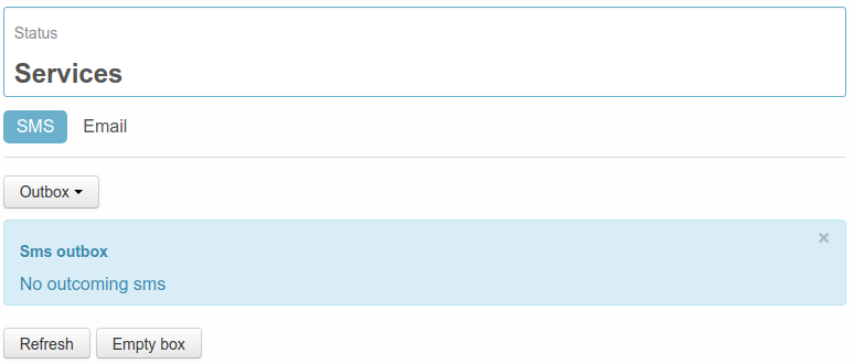
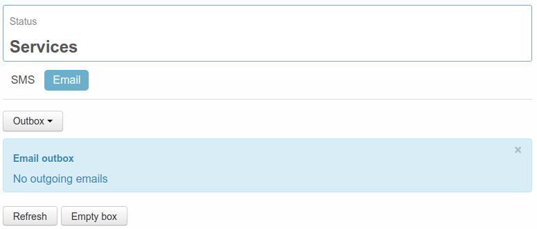
Clicking on the drop-down menu on the top of the table, it’s possible to pass from Inbox to Outbox.
On this table is possible to display all the messages not yet delivered by the WE200.
The available information are the following:
- Number: refers to the phone number of the message receiver
- Creation date: shows the date and time when the message has been created
- Text: displays the text of the message
The button Refresh can be clicked at any time in order to update all information; Empty box for deleting all messages available on Outbox (such messages won’t be delivered).
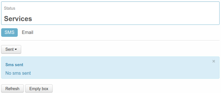
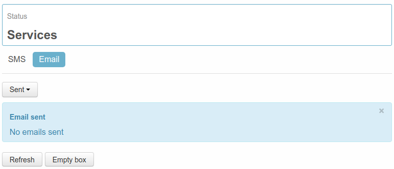
Clicking on the drop-down menu on the top of the table, it’s possible to pass from Outbox to Sent.
On this table are displayed some information regarding the SMS already delivered by the WE200:
- Number: shows the receiver of the delivered messages
- Send date: displays the date and time when the WE200 has delivered the message
- Text: contains the text of the sent messages
The button Refresh can be clicked at any time in order to update all information; Empty box for deleting all messages stored on Sent.
3.1.2. LAN connection
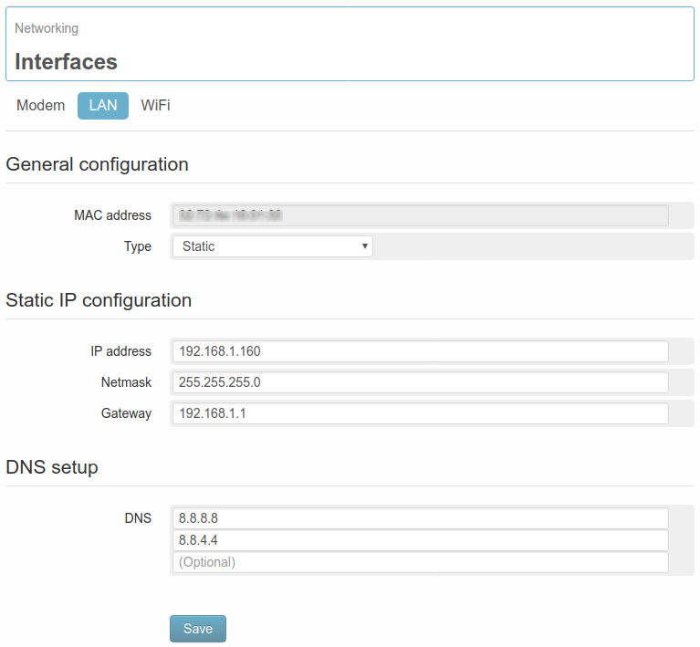
On the page Networking → Interfaces → LAN it’s possible to modify all parameters of the Ethernet interface.
First of all the MAC address of the device will be displayed, with the option of using the LAN network on static IP address or on DHCP.
If the Static address will be selected, the following parameters must be set for the correct operation of the service:
- IP address static IP address assigned to the WE200. Make sure that the address is available and not used on other devices.
- Netmask Subnet mask. A valid netmask must be entered, according to the specifications of the own local LAN.
- Gateway Network gateway
- DNS DNS that can be assigned to the WE200 ( max. 3)
After settings modification the WE200 requires a reboot in order to activate them. If the entered parameters are correct, it’s possible to enter the web interface of the WE200 (even remotely if the network allows it), to send emails and send data to a Portal/Server.
Further information regarding the status of the connection can be found on page Diagnostics → Networking (8.2. Information of connectivity)
3.1.3. Wi-Fi connection
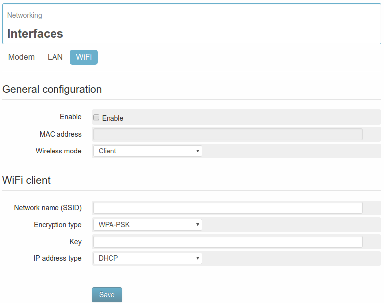
The page Networking → Interfaces → WiFi is available only if, at order confirmation, the option Wi-Fi on USB Port has been selected.
In this case it’s possible to configure the WE200 in order to let it connect to an existing Wi-Fi network.
First of all it will be displayed the MAC address of the Wi-Fi device connected to the WE200, then the access data of the Wi-Fi network where the WE200 has to get connected to, have to be defined:
- Network name SSID: Complete name of the Wi-Fi network
- Encryption type: Encryption of the access key
- Key: type of key/password for the authentication
It will also be given the possibility to choose between a static or dynamic Ip address in the field IP address type.
Choosing the static IP address, all necessary parameters for a proper functioning of the service will be required:
- IP address: static IP address assigned to the WE200. Make sure that the address is available and not used on other devices.
- Netmask: Subnet mask. A valid netmask must be entered, according to the specifications of the own local LAN.
- Gateway: Network gateway
After clicking on Save, the WE200 starts to scan the on-site available Wi-Fi networks. Once found the network with the previously set SSID, the WE200 will make the authentication using the indicated parameters.
If all operations will be successful executed, the indicators on the status panel will become green.
The WLAN network allows all operations permitted by the LAN network (remote access to the web server, data sending, email sending).
For further information regarding the status of the LAN connection, it’s possible to enter the page Diagnostics → Networking on section WLAN Interface (see 8.2. Information of connectivity).

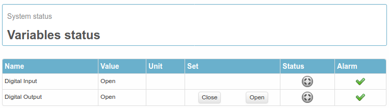
 or gray
  , according to the status and configuration of the variable.
 indicates that no active alarms are available. The icon
  indicates on the other hand the presence of an event configured as an alarm.
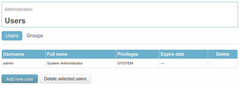
 The product shall not be treated as household waste. It shall be instead handed over to an appropriate collection point for the recycling of electrical and electronic products. For further information about recycling of this product, contact the local city office and/or the local waste disposal service.