2. Variables
A variable indicates the value of one parameter of the monitoring/control system.
For example, the variable called temperature indicates the value of the temperature measured by an analogical probe. WE500 allows to create variables and connect them to events and actions.
Variables are fundamental elements of the system, since they indicate the value of the monitored parameters and allow to send notifications, save logs, create charts and tabs, send data to Portal and so on.
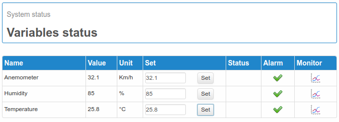
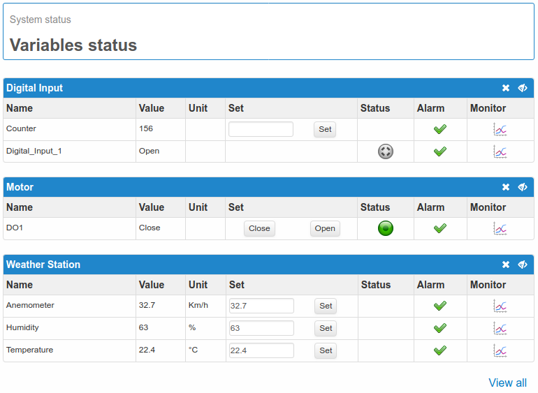
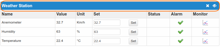
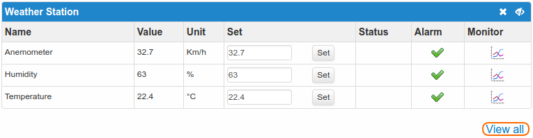
The variables and their status are displayed in alphabetical order or in groups on the page Status → Variables Status.
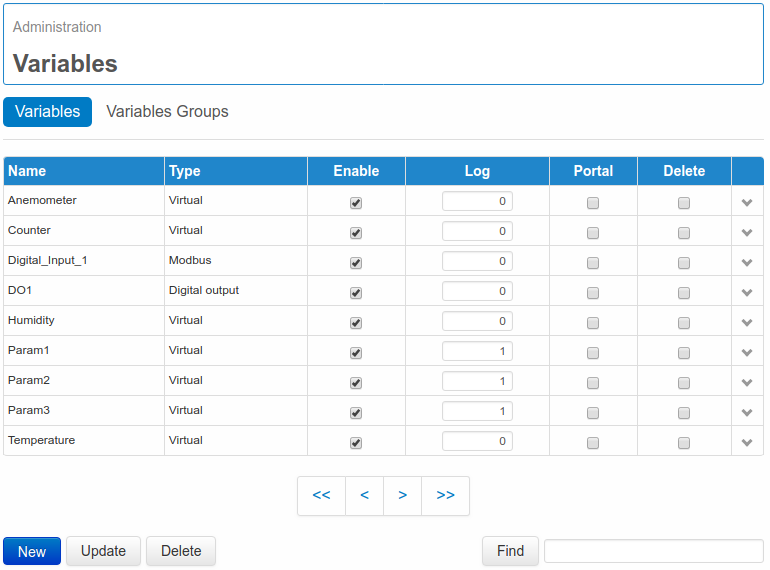
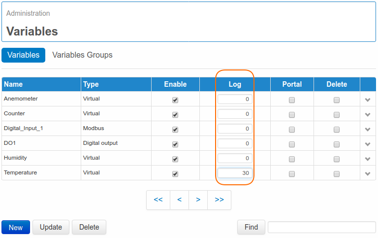
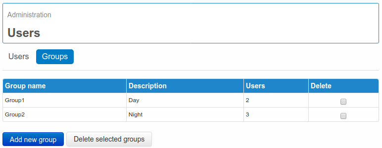
On page Administration → Variables → Variables is possible to create a new variable or to modify an existing one.
If variables are already defined, they will be displayed on a table showing some of the most relevant information. From this page is possible to disable a variable (and consequently any events and actions associated with it), to cancel it, to enable/disable the data sending to a Portal or to create a new one by clicking on New. For a quick selection of the desired variable/s is possible to use the function Find, that allows to search by name.
2.1. Generic variables
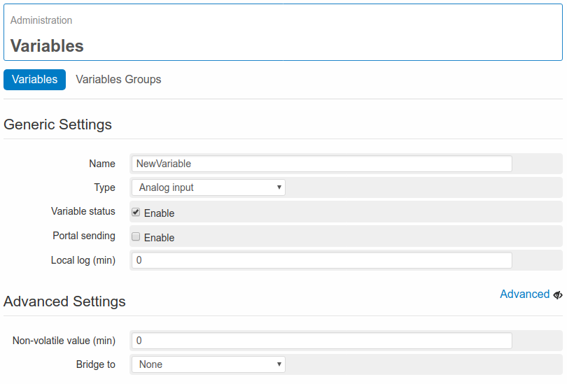
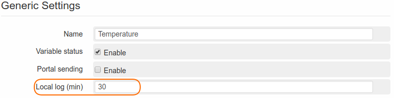
Many different types of variables are available, and for each of them parameters may differ. Only the section Generic Variable is valid for all types of variables. This section is structured as follows:
- Name: The name to be assigned to the variable. All alpha-numeric characters, and the character “_” are supported.
- Type: This allows to select the type of the variable. For each variable type the setting-parameters are different, see chapter 2.2. Type.
- Variable Status: enable/disable the variable
- Portal sending: it allows to enable/disable the sending of the variable value to an external portal/server. For further information regarding the data-sending, see relevant section 7. Data sending data sending.
- Non-volatile value: it allows to save the variable value every X minute and every time the device is switched off or rebooted.
- Skip first read: enabling this optional function the system won’t read the first value of the variable. For example, if an event has been defined on the variable, and at the reboot of the system the variable is in alarm status, through this optional function no action will be enabled.
- Local log (min): it allows to set a different sampling time (in minutes) for each variable. The recorded data can be then exported or displayed in charts or tabs. For further information see section 8. Datalogger.
2.2. Type
Here are the different types of variables:
- Analog Input: Variables associated to the analogue inputs available on the WE500. AI1 has to be selected to associate the variable with the analogue input 1 (connectors AN1 and GND) while AI2 has to be selected to associate the variable with the analogue input 2 (connectors AN 2 and GND). Further information on paragraph 2.3. Analog input variables (AI).
- Digital Input: Variables associated to the digital inputs available on the WE500. It’s possible to choose among DI1, DI2, DI3, DI4, DI5, DI6, DI7 and DI8. Further information on paragraph 2.4. Digital input variables (DI).
- Digital Output: Variables associated to the digital (relay) outputs available on the WE500. Select DOUT1 for the digital output 1 (connectors RL1A and RL1B) or DOUT2 for the digital output 2 (connectors RL2A and RL2B). Further information on paragraph 2.5. Digital output variables (DO).
- Modbus: Variables associated to modbus registers. Further information on paragraph 3.2. Creation of Modbus variables.
- Virtual: these are virtual variables that can be created in order to manage alarms or elaborate formulas. Further information on paragraph 2.6. Virtual variables.
2.4. Digital input variables (DI)
In order to create a DI Variable, i.e. associated to one of the digital inputs available on WE500, enter the Administration → Variables page. Clicking on New, it’s possible to enter the variable configuration page.
Select Digital Input on the field Type. Under the section Generic Variables all standard settings for any type of variable are available
For the description of all the fields of this section, see 2.1. Generic variables.
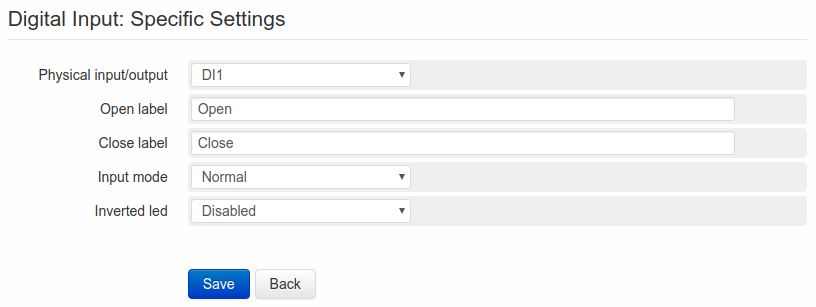
Let’s skip into the section Digital Input: Variable Specific Settings.
First of all is requested to confirm the digital input to be associated to the variable. It’s possible to choose among DI1, DI2, DI3, DI4, DI5, DI6, DI7 and DI8. Irrespective of the selected input, the fields Close label and Open label need to be completed. Close label refers to the value (or status), that will be displayed when the relevant digital input is closed, Open label refers to the open input. For WE500 a closed Digital Input variable has a logic value of 1. In case of an open input, the logic value is 0. This becomes a very important information for the definition and setting of the events.
Once filled in above mentioned fields, the operating mode has to be selected in the Input mode field choosing among the following options:
- Normal
- Counter
- Flow measurement
- Time counter
Depending on selection, the meaning of the following fields will change.
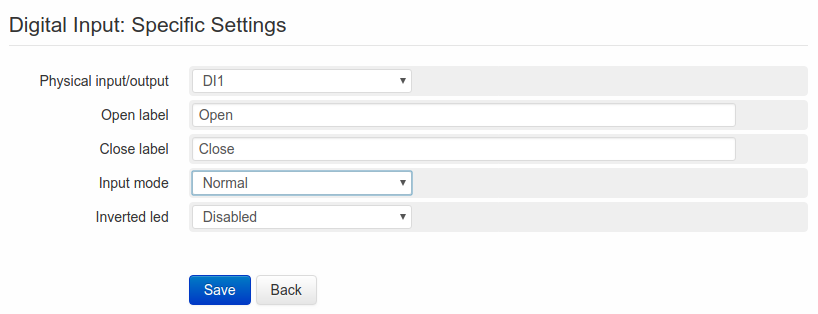
2.4.1. Normal
A DI → Normal type variable allows to display the status of the digital input. It is then possible to define events/actions connected to the status change (from open to closed and vice-versa).
The only additional field to be configured is the Inverted led. This can change the visualization of the variable on the page Status → Variables Status. If this option is disabled, the open status of the input will be associated to a grey spot, while the closed status to a green one. With enabled option, the situation will be the opposite. For further information see relevant section 6.1. Variables status.
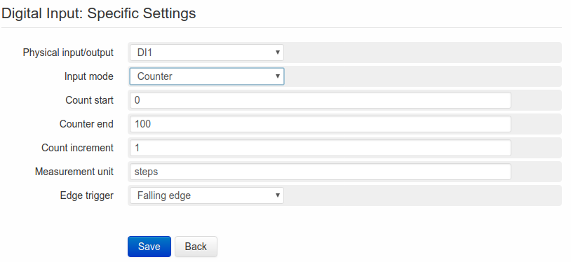
2.4.2. Counter
A DI → Counter type variable allows to count impulses on a digital input.
The first field to be completed is Count start, i.e. the starting point of the counter. This value will be considered only the first time: if the counter should be reset, it would then restart from 0.
- Counter end refers the maximum limit to be reached for resetting the counter. If this field is configured at zero, the counter will increase indefinitely without reverting to zero.
- Count increment is the increment unit value of each impulse of the counter.
- Measurement unit is the unit of measurement assigned to the counter. This will be displayed on charts and on the page Status → Variable Status.
The last field to be configured is Edge trigger, i.e. the edge to be considered for the impulse.
Selecting Falling edge the counter will increase when the input changes form closed to open; selecting Rising edge the counter will increase when the input changes from open to closed;
selecting Rising and falling edge the counter will increase at every edge changing.
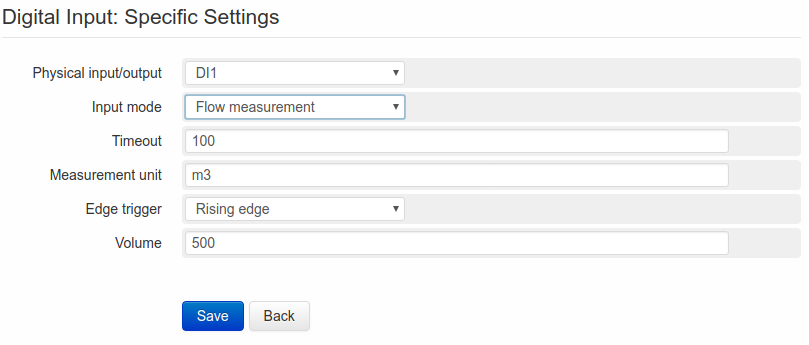
2.4.3. Flow measurement
A DI → Flow measurement type variable allows to calculate the flow rate.
In the Timeout field is entered the max. interval of time (expressed in seconds) between two impulses. Once the configured interval of time has passed, the variable will be reset to 0. This function can be useful in case, that the flow should stop for unexpected reasons. If no timeout value is set, the variable value would be the one of the last received impulse, and would therefore be giving wrong information at request and potentially generate incoherent logs.
In the Volume field is set the sample unit, to be associated with an impulse.
Measurement unit allows to set a unit of measurement for this variable, in Edge Trigger is possible to select the edge to be considered as an impulse: Falling edge if the changing from closed to open input has to be considered and Rising Edge for the contrary and Rising and falling edge for both of them.
EXAMPLE:
Assuming the following configuration with timeout at “600”(seconds), Rising edge, unit of measurement L/s (Liters per second) and volume at 100, the situation will be:
- The input changes from open to closed; WE500 starts counting
- The input changes from closed to open
- The input changes from open to closed after 20 seconds
- WE500 calculates the sample volume (100) for the passed time (20 seconds) and displays therefore a result of 5L/s
- The input doesn’t change its status for at least 600 seconds
- WE500 reset the variable and waits for new incoming impulses before start counting again.
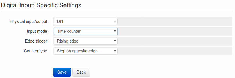
2.4.4. Time counter
A DI → Time counter type variable allows to count the opening/closing time of a contact (expressed in seconds). This variable can be used for calculating the total operating time of a defined machinery.
After the configuration of the Edge Trigger (reminding that Falling edge refers to the change from closed to open, Rising edge refers to the opposite and Rising and falling edge to both of them) the type of counter has to be selected among following possibilities:
- Permanent: After the start of the counter, WE500 will increase the value at every second, until the user will reset it
- Stop on opposite edge: the counting will start at the occurrence of an edge change according to the choice made on the relevant field; the counting will stop when reaching the opposite edge and restart again at next change.
- Reset on opposite edge: the counting will be reset when reaching the opposite edge, and restart from 0 when the selected edge will be reached again.
2.5. Digital output variables (DO)
In order to create a DO variable, i.e. associated to one of the digital outputs available on WE500, enter the page Administration → Variables.
Clicking on New, it’s possible to enter the variable configuration page.
Select Digital Output on the field Type.
Under the section Generic Variables all standard settings for any type of variable are available.
For the description of all the fields of this section, see 2.1. Generic variables.
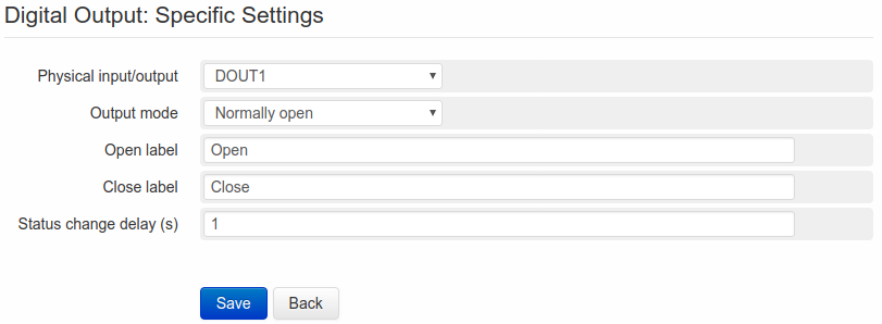
Let’s skip into the section Digital Output: Variable Specific Settings.
After the selection of the Output (between DOUT1 and DOUT2) to be associated to the variable to be created, it’s required to set the operating mode in the Output mode field.
The available options are:
- Normally open: The output is normally open. Open label refers to the open status of the contact. Close label will close the contact.
- Normally closed: The output is normally closed. Open label refers to the open status of the contact. Close label will close the contact.
- Pulse open: The output operates in pulse mode. Open label refers to the open status of the contact. Close label will close the contact. Once closed, the outputs keeps this status for the time configured on the field Pulse duration, after that it returns automatically to the open status.
- Pulse closed: The output operates in pulse mode. Open label refers to the open status of the contact. Close label will close the contact. Once opened, the outputs keeps this status for the time configured on the field Pulse duration, after that it returns automatically to the closed status.
Regardless of the selected option, the field Status change delay(s) must be filled in with the number of seconds of delay required between an impulse and the enabling/disabling of the output.
Please note that the Non-volatile value option can be combined with the Output mode.
If this option is not enabled, the start output status after a power-off or reboot will depend on the Output mode, i.e.: in case of Normally open/Pulse open output, the contact will start from open status; in case of Normally closed/Pulse closed output, the start of the contact will be from closed status.
On the other hand if the non-volatile value option is enabled, the start output status will be the same as at the power-off or reboot of the system.
The status of the digital outputs can be modified through their association to an event either by an SMS command or directly from the page Status → Variables status.
2.6. Virtual variables
Virtual variables are not connected either to I/O or to modbus. These variables can be managed via SMS, EMAIL or from Status -> Variables status status, they can also be associated to an event or can be determined through a mathematical expression.
In order to create a Virtual variable enter the page Administration → Variables.
Clicking on New, it’s possible to enter the variable configuration page.
Select Virtual on the field Type.
Under the section Generic Variables all standard settings for any type of variable are available
For the description of all the fields of this section, see 2.1. Generic variables.
Let’s skip into the section Virtual Variable: Virtual variable: Variable Specific Settings.
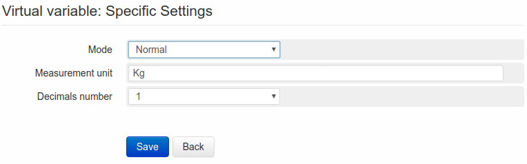
Two types of virtual variables are available:
- Normal: Once set the unit of measurement on the field Measurement unit and the number of decimals on Decimals numbers, it’s possible to save the variable. Its value can be changed manually (via SMS, Email or from Status → Variables status) and/or automatically (as execute command on the page of events creation, see 4.2.3. Execute command).
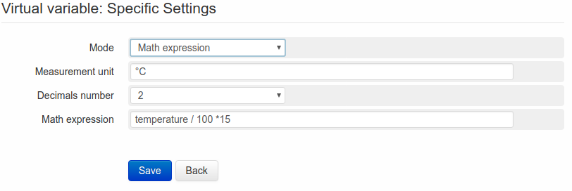
- Math expression: Once entered the unit of measurement on Measurement unit and the number of decimals on Decimals numbers, its possible to define a mathematical expression to be applied to the variable.
A Virtual variable with Math expression allows to make calculations using variables or constants and to use some of the most common mathematical operations, as for example:
- Addition (+)
- Subtraction (-)
- Multiplication (*)
- Division (/)
- Exponentiation (^)
- Squared root (sqrt)
- Logarithm (log)
- Sine (sin)
- Cosine (cos)
or constants as:
- e(e)
- logarithm base 2 of e (log2e)
- logarithm base 10 of e (log10e)
- squared root of PI (2_sqrtpi)
- squared root of 2 (sqrt)
- squared root of 1/2 (sqrt1_2)
The use of round brackets is supported.
EXAMPLE 1:
“Var1” is the name of a variable of any type (not necessarily a Virtual variable) and its value is 10. In the field Math expression we could write:
Var1^2
In this case the Virtual variable would have a value of “100”.
EXAMPLE 2:
Var1 as above
Var2 is another variable of any type and its value is 15
In the field Math expression we could write:
( Var1 * ( Var2 – 10 ) ) / 2
obtaining (10 * (15-10)) / 2 → (10*5)/2 → 50 / 2 → 25
The value displayed by WE500 will therefore be “25”.
Changing one of the expression’s factors, the result is automatically recalculated by the WE500.
A Math expression Virtual variable can be used as a element inside another expression.
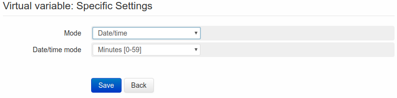
- Date/Time: This variable type will display seconds, minutes, hours, month’s day, month, year, day of the week, or day of the year.
Selecting for example Minutes [0-59] on the field Date/time, when it’s 12:35, the variable will show the value 35.
2.7. Bridge between variables
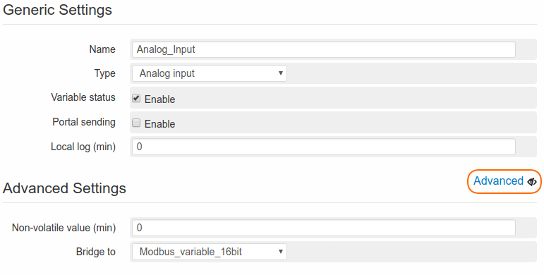
WE500 allows to create bridges between variables, in order to transfer the value or the status of a given variable to another variable. This type of function is very useful when it’s required to read via modbus the values of the variables associated to the I/O of WE500.
Assuming for example, that it’s required to read the value of the analogue input “1” of the WE500 on any Master device, the following operations have to be executed:
- Click on the drop-down menu and select the previously created 16 bit modbus variable from the list.
- Associate the 16bit modbus variable to a modbus command and to a Slave network (3.1. Master/Slave Modbus)
Through this procedure two variables will have the same value. At every status/value change of the Analog Input variable will correspond a similar change of value of the modbus variable.
3. Modbus
Modbus is a communication protocol used for industrial systems. The graphical interface and the sequence of pages and sections of the WE500 make the modbus configuration very easy and intuitive under all aspects.
WE500 allows to create two types of modbus networks:
- Master, in order to read/write registers of a slave device
- Slave, in order to make available the own data to a master device
To create a functioning modbus network is necessary to:
- Create one or more modbus variables
- Create one or more modbus commands
- Set the communication parameters of the modbus network
- Associate the variables and the commands with a modbus network
There is no predetermined sequence: it can be started by defining the network parameters and then creating variables and commands or starting with the creation of commands and variables and then associate them later on.
3.1. Master/Slave Modbus
WE500 allows to create an unlimited number of Modbus networks irrespective of the type (master/slave) or of the physical network (TCP/IP, 232, 485).
This allows to have a system, where the WE500 acts as Master in some networks and as Slave in some others at the same time.
The separation between Master and Slave network is available only in the definition of the modbus network (Administration → Modbus → Networks)), while variables and commands can be defined on the same way. For example, a 16bit variable and its relevant reading command Read holding registers-0x03 can be created without specifying if they refer to a Master or a Slave network. Defining the network, two are the possible scenarios:
- Master: the WE500 will try to read the register associated to the variable, using the previously defined command.
- Slave: the WE500 will allow any Master device to read the register associated to the variable, using the previously defined command.
3.2. Creation of Modbus variables
To create a variable (of any type) enter Administration → Variables → Variables.
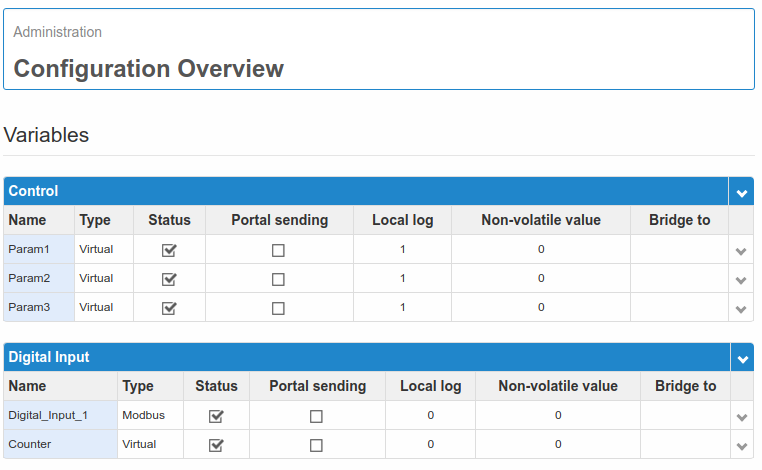
If some variables are already available, they will be displayed in the table with some of their main features.
To edit an existing variable click on its name, to create a new one click on New.
The name of the new variable is entered in the page for creating variables: the field Name accepts alpha-numeric characters and “_”. The space is not allowed.
Then select Modbus in the Type field.
Under the section Generic Variables all standard settings for any type of variables are available
For the description of all the fields of this section, see 2.1. Generic variables.
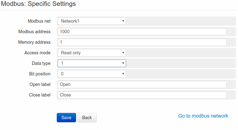
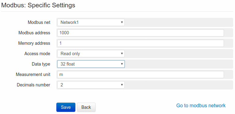
According to the type of variable selected, the following section will have a specific structure:
- Modbus net: It allows to select a modbus network to be associated with the new variable to be created. If no modbus network is available, this field must be left blank.
- Modbus address: If the variable has to be associated to a Master network, this field must be completed with the slave address of the device to be interrogated by the WE500. If the variable has to be associated to a Slave network, this field must be completed with a generic address, that the Master will interrogate to communicate with the WE500.
- Memory address: this field must be completed with the memory register, to be associated with the variable.
It’s now necessary to select the Access mode, i.e. the type of modbus variable, among the following options:
- Read only: It’s possible to read the variable value but not to change it
- Write only: It’s possible to edit the variable value but not to read it.
- Read and write: The variable value can be read and edited.
In the field Data type is possible to select the variable number of bit.
3.2.1. 1 bit data type
In this field is requested to specify the position of the bit inside the word (1word=16 bit). Inside one single word there can be up to 16 variables of 1 bit each. If the variable, that we want to create, is on the first position of the word, the value “0” must be selected in the field Bit position. Alternatively if the variable, that we want to create, is on the last position of the word, the value “15” in the field Bit position must be entered.
In order to complete the creation of the variable, just set up a string for the open status (corresponding to value 0) and a string for the closed status (corresponding to value 1). These strings will allow to display the variable status (for example Open/closed, on/off, and so on..)
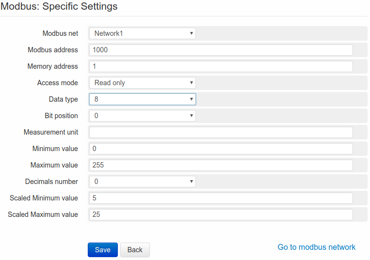
3.2.2. 8 bit data type
For the 8 bit variables is requested to specify the Bit position (it’s possible to choose only between 0 and 7, since 8 bit corresponds to half a word) and some other information available also for 16-32-32inv variables. If the variable, that we want to create, is in the first word position, the value “0” must be entered in the field Bit position. Alternatively if the variable, that we want to create, is in the middle of the word, the value “7” must be entered in field Bit position.
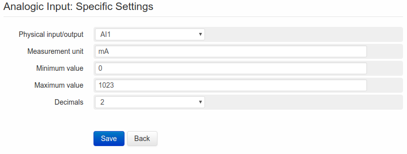
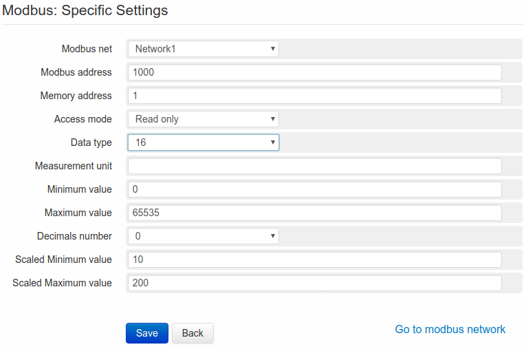
3.2.3. 16-32 bit data type
Selecting 16, 32 or 32inv on the field Data type, the following fields must be completed and specified:
- Measurement unit: measurement unit selected to be assigned to the variable
- Decimals number: quantity of decimal numbers to be displayed
- Minimum value: set the minimum (normally “0”) according to the type of variable
- Maximum value: set the maximum (for example 65535 for 16 bit variables) according to the type of variable.
- Scaled Minimum value/Scaled Maximum value: the two above mentioned fields are necessary for a correct interpretation of the read/written data by the WE500, even though they might not be relevant for the end-user.
Selecting 16, 32 or 32inv on the field Data type, the following fields must be completed and specified:
- Measurement unit: measurement unit to be assigned to the variable
- Decimals number: quantity of decimal numbers to be displayed
- Minimum value: set the minimum (normally “0”) according to the type of variable
- Maximum value: set the maximum (for example 65535 for 16 bit variables) according to the type of variable.
- Scaled Minimum value/Scaled Maximum value: the two above mentioned fields are necessary for a correct interpretation of the read/written data by the WE500, even though they might not be relevant for the end-user.
Assuming for example a 16 bit variable with min./max. values of respectively 0/65535: a user should need to measure a level from 0 to 10 meters. To this purpose it’s enough to set “0” as Scaled Minimum value and “10” as Scaled Maximum value.
3.2.4. 32 bit float data type
For the 32Float/32Float inv variables it’s necessary to set the measurement unit and the number of decimals. This type of variable doesn’t require any scaling.
By clicking Save the variable will be created.
Note
Information as Modbus address, Memory address, Access mode, Data type, Bit position are normally described in the data sheets of the modbus devices.
It’s important to make sure that all parameters are correct, in case of doubts contact the salve device’s manufacturer or the Support at Nethix.
For further information about the use of the Modbus Protocol, visit the official site modbus.org.
The following step is to create a modbus command, suitable to interact by reading or writing with the new created variable. In order to enter the section dedicated to the modbus commands, select Administration → Modbus → Commands on the menu.
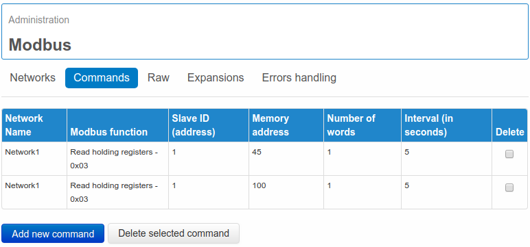
3.3. Creation of Modbus commands
All modbus variables need to be associated to a read or write command.
Under the section Administration → Modbus → Commands all available commands (if previously created) will be displayed. In order to create a new command click on Add new command.
According to the type of created variable it’s possible to define a read/write command using one of the following functions:
- Read coils -0x01
- Read holding registers -0x03
- Read input registers -0x04
- Write single coil -0x05
- Write single register -0x06
- Write multiple registers -0x10
All functions available in WE500 respect the Modbus standard.
Once made the selection of the function to be used, the following parameters need to be set:
- Slave address: it’s the address of the slave device, where to send all requests/writings. This address must be the same as the one entered in the field Modbus address, previously set in the variable configuration.
- Memory address: it’s the memory address associated to the command. This must be the same as the one previously entered in the field Memory address of the variable.
- Words number: it’s the number of word where to use the command. Some functions allow to enter more than one word (to be checked on slave device’s documentation). Setting for example “1” as Memory address and “10” as Words number, it should be possible to use one single command to enter 10 consecutive registers.
- Interval: Interval of time for the reading function. For the write function this option is not available (the writing of a register is enabled at request). Setting for example “5”, the reading of one or more registers/word is executed every five seconds.
- Modbus Networks: If one or more Modbus networks have already been created, it’s possible to select the one to be associated with the created command.
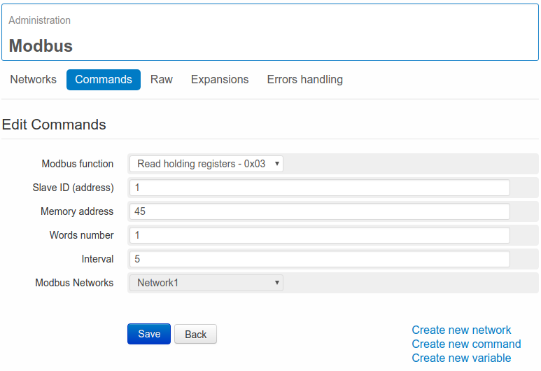
Clicking on Save the command will be saved.
Note
Information as Modbus address, Memory address, Access mode, Data type, Bit position are normally described in the data sheets of the modbus devices.
It’s important to make sure that all parameters are correct, in case of doubts contact the salve device’s manufacturer or the Support at Nethix.
For further information about the use of the Modbus Protocol, visit the official site modbus.org.
Once created the command, it’s possible to proceed with the definition of the modbus network. To enter this section, select Administration-> Modbus-> Networks from the menu, click the tab Networks on the top left side or click the link Create new network on the right side of the Save button.
In this last case, when the page for the creation of modbus networks opens, the new created command is already associated with the network.
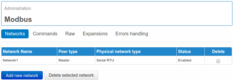
3.4. Modbus network creation
All modbus variables and commands need to belong to a modbus network to grant a correct functioning. WE500 supports several modbus networks of different physical types.
Selecting Administration → Modbus → Networks from the menu, an overview of all available networks will be displayed.
It’s possible to create a new network clicking on Add new network.
Through the fields Peer type and Physical network type is possible to get 4 different combinations:
- Master-RTU
- Slave-RTU
- Master-TCP
- Slave-TCP
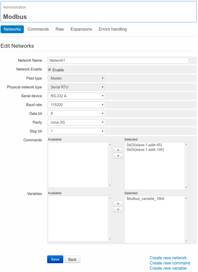
3.4.1. Master - RTU Modbus network
According to this combination the WE500 will act as Master inside a RTU network, using one of the available serial ports in order to read/write on the registers of any modbus slave devices.
The settings to be defined are the following:
- Network Name: it’s the name to be assigned to the network. Alpha-numeric characters and the character “_” are supported.
- Network enable: Enable/Disable the network. By disabling an enabled network all associated commands will be canceled. Thus all the variables associated to the network will cease to be updated.
- Peer type: Master
- Physical Network type: Serial RTU
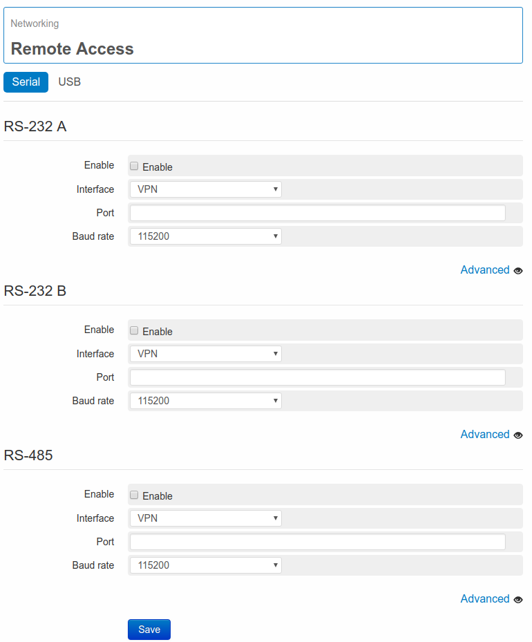
- Serial device: it allows to select one of the following serial ports:
- RS-232 A (connectors TX1, RX1, GND)
- RS-232 B (connectors TX2, RX2, GND)
- RS-485 (connectors A, B, GND)
- Baud rate: Data transmission speed rate. This field is available in case of RTU Serial.
- Data bit: Number of data bit for each character (normally 8).This field is available in case of RTU Serial.
- Parity: Bit of Parity. This filed is available in case of RTU Serial.
- Stop bit: Number of stop bit. This field is available in case of RTU Serial.
3.4.2. Slave - RTU Modbus network
According to this combination the WE500 will act as Slave inside a RTU network, using one of the available serial ports in order to receive commands from the connected master device.
The settings to be defined are the following:
- Network Name: it’s the name to be assigned to the network. Alpha-numeric characters and the character “_” are supported.
- Network enable: Enable/Disable the network. By disabling an enabled network all associated commands will be canceled. Thus all the variables associated to the network will cease to be updated.
- Peer type: Slave
- Physical Network type: Serial RTU
- Slave address: slave address to be associated to the WE500
- Serial device: it allows to select one of the following serial ports:
- RS-232 A (connectors TX1, RX1, GND)
- RS-232 B (connectors TX2, RX2, GND)
- RS-485 (connectors A, B, GND)
- Baud rate: Data transmission speed rate. This field is available in case of RTU Serial.
- Data bit: Number of data bit for each character (normally 8).This field is available in case of RTU Serial.
- Parity: Bit of Parity. This filed is available in case of RTU Serial.
- Stop bit: Number of stop bit. This field is available in case of RTU Serial.
3.4.3. Master - TCP Modbus network
According to this combination the WE500 will act as Master inside a TCP network, using one of the available network interfaces in order to read/write on registers of any modbus slave devices.
The settings to be defined are the following:
- Network Name: it’s the name to be assigned to the network. Alpha-numeric characters and the character “_” are supported.
- Network enable: Enable/Disable the network. By disabling an enabled modbus network all associated commands will be canceled. Thus all the variables associated to the network will cease to be updated.
- Peer type: Master
- Physical Network type: Ethernet TCP
- IP address: IP address of the slave where the WE500 has to connect.
- Port: Slave access Port.
3.4.4. Slave - TCP Modbus network
According to this combination the WE500 will act as Slave inside a TCP network, using one of the available network interfaces in order to receive reading/writing commands from any master devices.
The settings to be defined are the following:
- Network Name: it’s the name to be assigned to the network. Alpha-numeric characters and the character “_” are supported.
- Network enable: Enable/Disable the network. By disabling an enabled modbus network all associated commands will be canceled. Thus all the variables associated to the network will cease to be updated.
- Peer type: Slave
- Physical Network type: Ethernet TCP
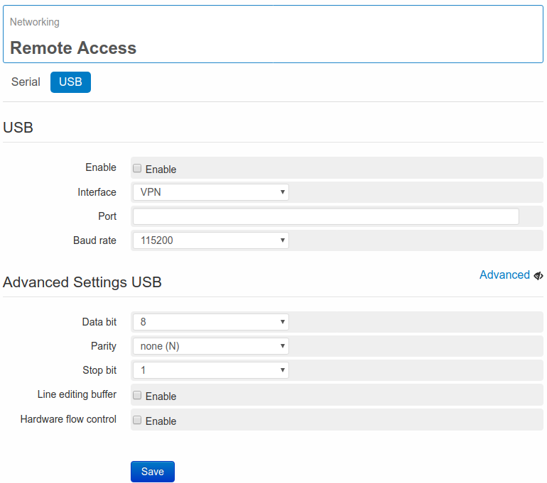
- Interface: It allows to select the network interface to be used by the WE500 in order to receive commands from the master device. The available options are: LAN, 2G/3G/4G, and VPN.
- Port: It’s the Port where the master device will interrogate the WE500
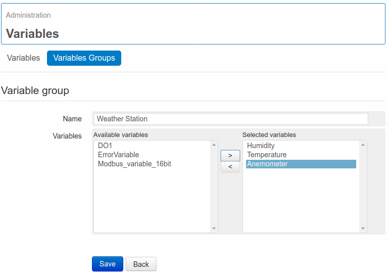
Regardless of the selections made on the fields Peer type and Physical network type, the previously created commands and variables have to be associated to the relevant network through the tabs commands and variables.
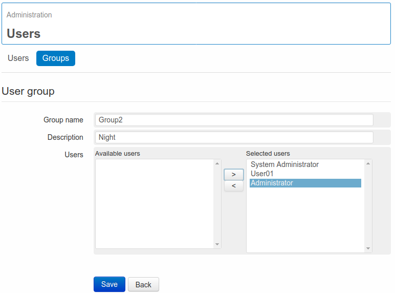
In the table Availables are listed all variables and modbus commands previously created. Selecting and clicking > (or with a double click on it), the variable or the command is moved to the table Selected.
To remove a variable or a command from the modbus network, select it and then click on < (or click twice on it)
When Save, without configuration errors, is clicked, the system will activate the new modbus network.
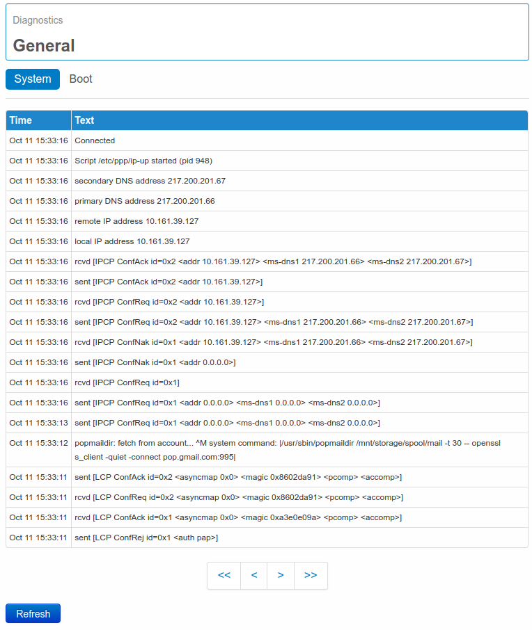
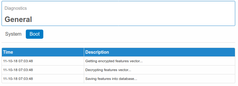
In order to check the correctness of all settings, it’s possible to check on page Status->Variables status or the system’s logs on page Diagnostics-> General.
Note that, once created a modbus network, on the left side of the tabs Save and Back some links will be available, these allow to enter directly the relevant pages, without passing through the menu:
- Create new network: clicking on this link, the field Name on the same page will be reset, allowing to create a new modbus network. All communication parameters of the previous network will be copied.
- Create new command: clicking on this link, there will be a redirection to the page of command creation. The command will be associated to the modbus network. Once saved the command, it’s possible to click on Create new command. Thus all fields will be reset and it will be possible to create a new command. The command will be assigned to the previously available network, but it will be possible to select a different network by changing the content of the field Modbus Network.
- Create new variable: through this link there will be a redirection to the page of variable creation. By default the field Type will be set at Modbus and Modbus Net will show the name of the available modbus network. Clicking on Save the variable will be automatically associated to the modbus network. At this stage is possible to click on Create new variable. The field Name will be reset, while all other fields will be duplicated. This procedure will speed up the creation of a new modbus variable especially if several similar variables are available (having the same Access mode, Data type, Open/Close label): in this case it will be enough to change only the name and just a few more specific parameters. Also in this case the variable will be at first associated with the previous modbus network.
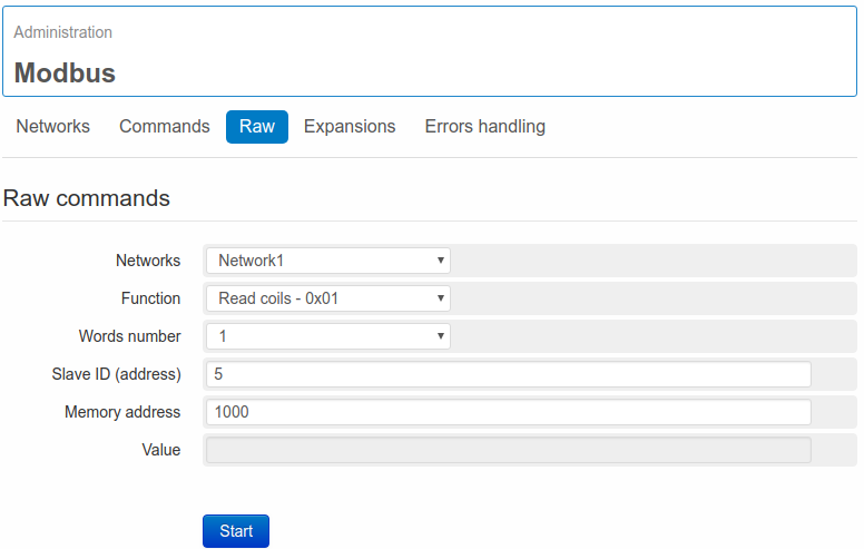
3.5. Instant reading
It’s possible to read or write one or more modbus registers without creating a variable or a command.
Entering the page Administration → Modbus → Raw, it’s possible to start an instant reading/writing of a given register, just by properly completing the following fields:
- Networks: Select a network among the available ones. This function is possible only if at least one network is already available.
- Function: Select the modbus function to be used in order to read or write the register/s.
- Words number: indicate the word number “1” in case of 1-8-16 bit variables, and the “2” in case of 32 bit or float variables.
- Slave address: indicate the slave address to be entered
- Memory address: indicate the memory address to be entered.
In the field Value it will be displayed the value read (in case of reading functions) and a notification message of successfully executed reading/writing will be sent by the WE500.
3.6. Modbus expansions
WE500 includes 8 digital inputs, 2 analogue inputs and 2 digital outputs. The I/O module of WE500 can nevertheless be expanded with one or more additional expansion units of the range XP500.
In order to add or edit an expansion unit is necessary to enter the page Administration → Modbus → Expansions and click on New or select one of the previously added expansions.
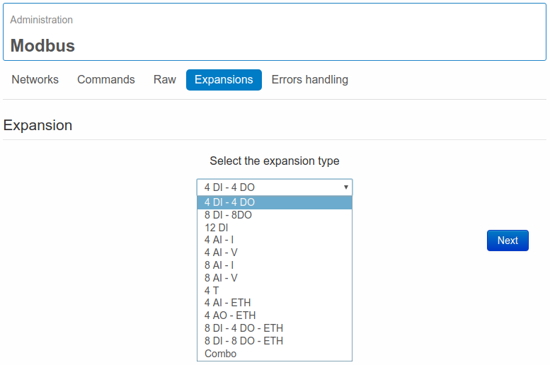
Click on New to enter the wizard, that allows to install any of the available expansion modules of the range XP500 and XP500/ETH.
The available models are:
- 4DI-4DO
- 8DI-8DO
- 12DI
- 4AI-I
- 4AI-V
- 8AI-I
- 8AI-V
- 4T
- 4AI-ETH
- 4AO-ETH
- 8DI-4DO-ETH
- 8DI-8DO-ETH
- Combo
For further details on the available models, refer to the specific manuals XP500/ETH and XP500.
Once made the selection of the required expansion type, clicking on Next, the guided installation procedure will start.
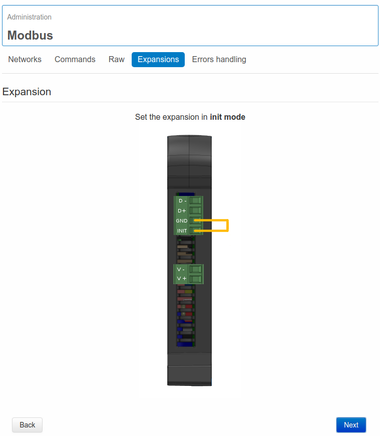
For each single model of XP500 and XP500/ETH the wizard will explain how to enter the Init Mode, which is necessary to let the WE500 connect to the expansion, when to turn on the device and how to connect it to the WE500 ( in case of RS485 expanders).
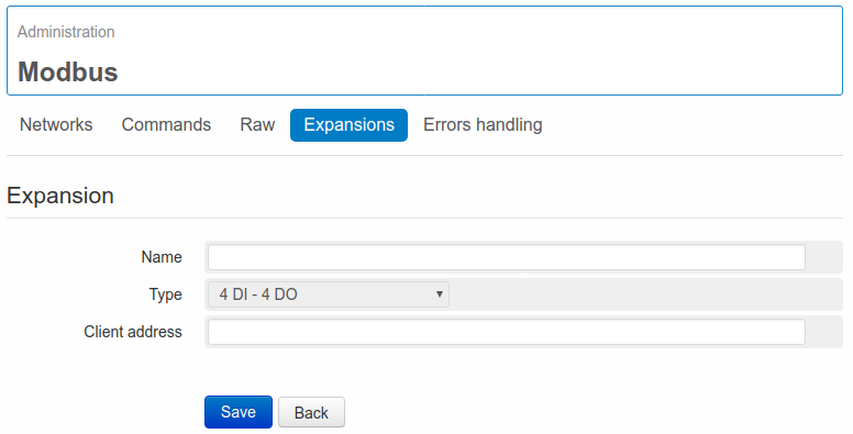
At the end of the procedure it’s required to confirm the name and client address:
- Name: it’s the name to be assigned to the expansion. This name will be used to create a variables group, where the variables of the inputs/outputs of the expanders will be included.
- Type: it will display the selected expansion model.
- Client address: it refers to the slave address to be assigned to the expander. The client address allows the expander to have a unique ID inside its Modbus network. This is a precondition, in order to let the WE500 identify the correct expanders, when more than one XP500/XP500-ETH are available. It’s recommended never to set the number “1” as client address.
Once clicked on Save, the WE500 will try to set inside the connected expander, the client address entered by the user. Then the WE500 will create automatically all variables and Modbus commands (and the network, if not already available) to communicate with the XP500.
The names of the variables can be modified later on.
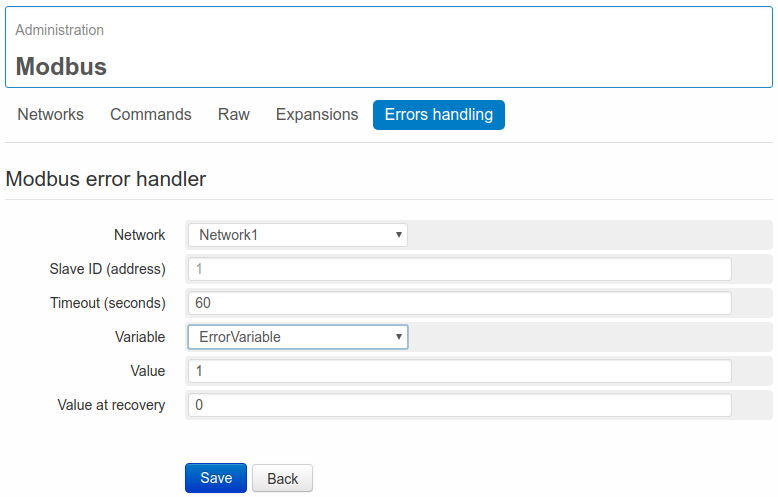
3.7 Manage Modbus errors
WE500 allows to manage the modbus errors on the page Administration → Modbus → Errors handling, clicking on new.
At the occurrence of a modbus error it’s possible to set a variable at a specific value:
- Network: the network where the error occurs
- Slave ID (address): the slave address to be monitored ( this field appears only in case of master networks)
- Timeout (seconds): the error is displayed only if available for more than X seconds
- Variable: the variable to be set. Selecting None, it’s possible to avoid the setting of any variable
- Value: the value, that the variable should assume at the occurrence of the error
Clicking on Save the error handling is configured and starts monitoring the errors that may occur on the selected network.
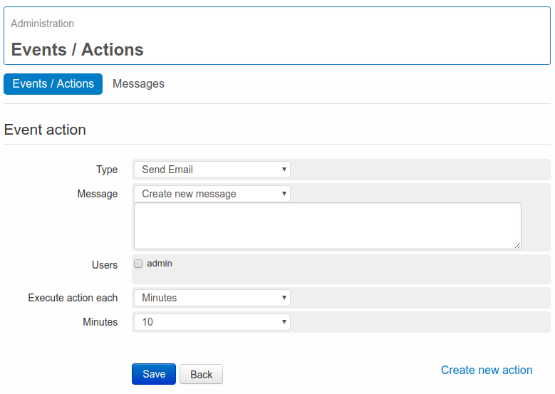
4. Events/Actions
Beside variables, events and actions are the other fundamental elements of the WE500.
An event allows the activation of an action when a variable reaches a certain value/status. For example, an event called warm_room can be intercepted when a variable called temperature is higher than 25°C.
An action is the consequence of the identification of an event. For instance when the event called warm_room is detected, an SMS can be sent to a preconfigured user.
WE500 allows to configure events, that can be associated to actions, in the case that a variable reaches a certain value or status.
4.1. Events
The events allow the WE500 to acknowledge when a monitored parameter reaches a relevant threshold for the user.
Different types of events are available and each type of event is composed of several parameters, in order to reach a high flexibility in controlling and monitoring the system.
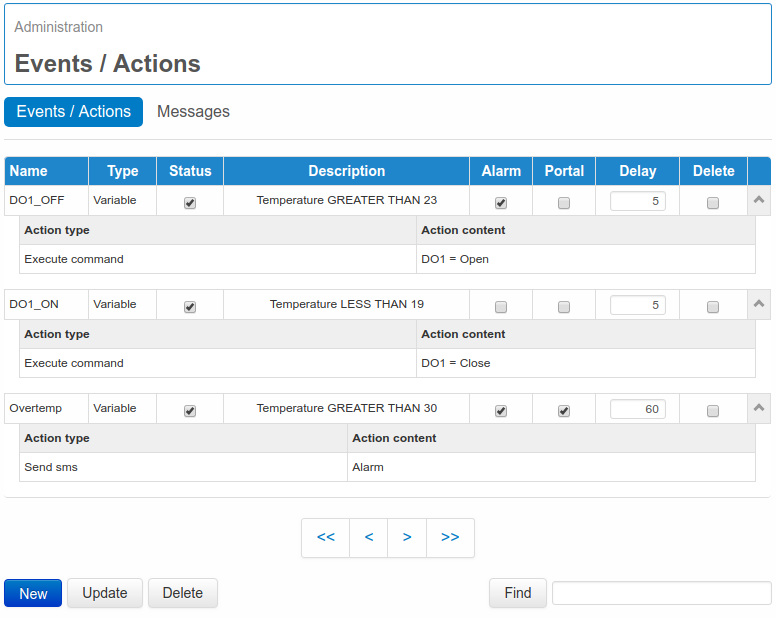
To create an event, enter the page Administration/Events/Actions and click on New.
The tab Delete allows to cancel one or more selected events. With the tab Update it’s possible to edit the enabling/disabling of one or more events, to configure events as alarms and send them to a web portal. For a quick search by name of one or more events the Tab Find can be used.
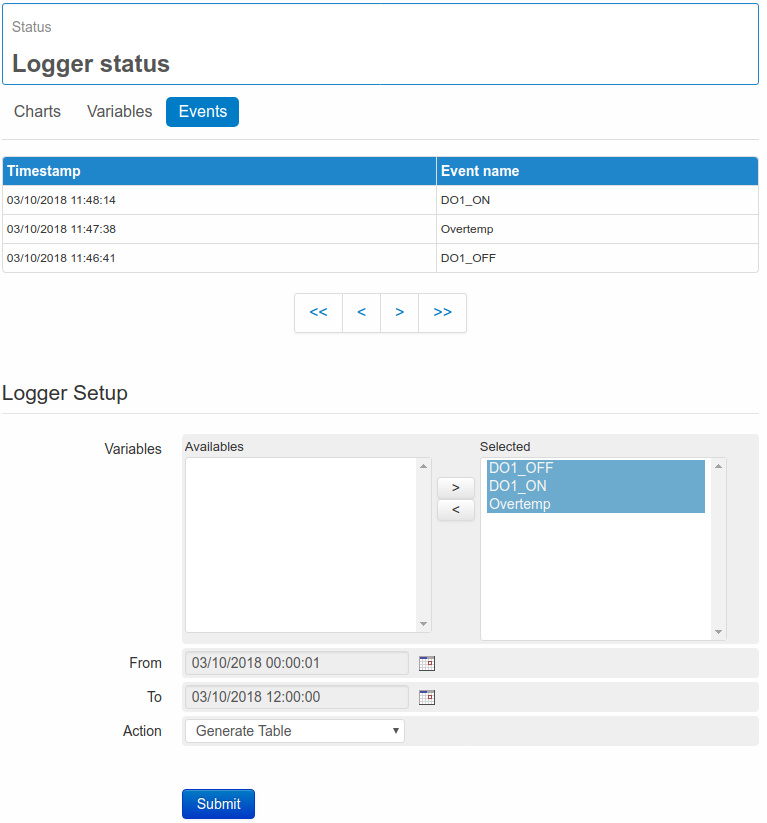
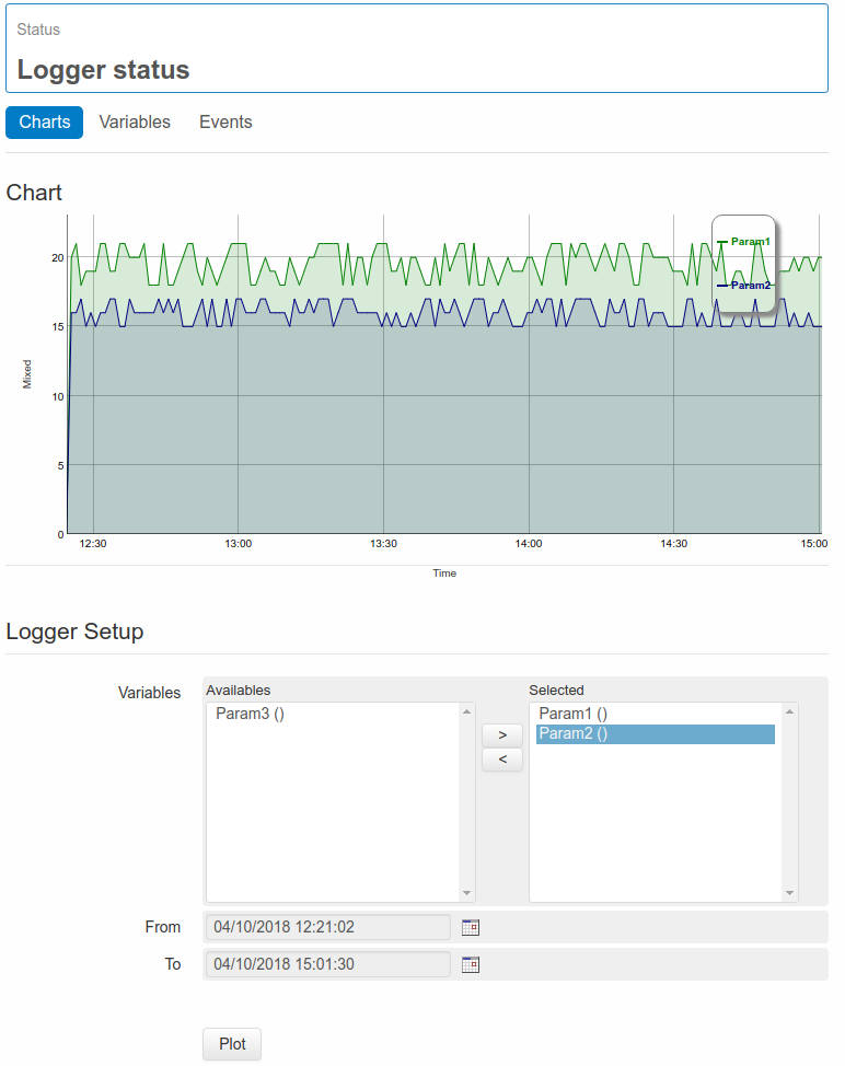
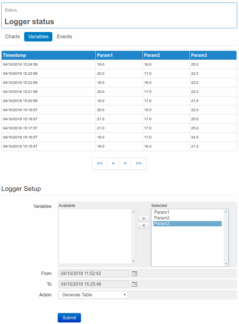
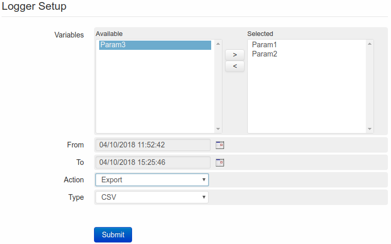
All occurred events can be displayed in a chronological chart, entering the page Status → Logger status → Events.
From this page it’s possible to display one or more events, by selecting them, and the time interval to be considered, from the relevant list, and possibly export data on CSV or Excel format.
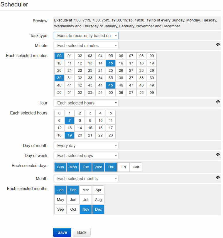
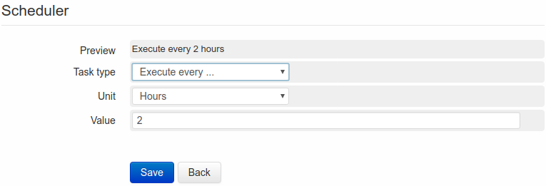
During the creation of an event, and after entering the name, must be selected the type of event among Variable, Events, Formula, Incoming data or Scheduler (see 5. Scheduler).
Some generic options can be activated according to the selected type of event: it’s possible to decide the enabling of the event from Status, the visualization as an alarm on the field Set as alarm and to send it to a web portal from the field Send to portal.
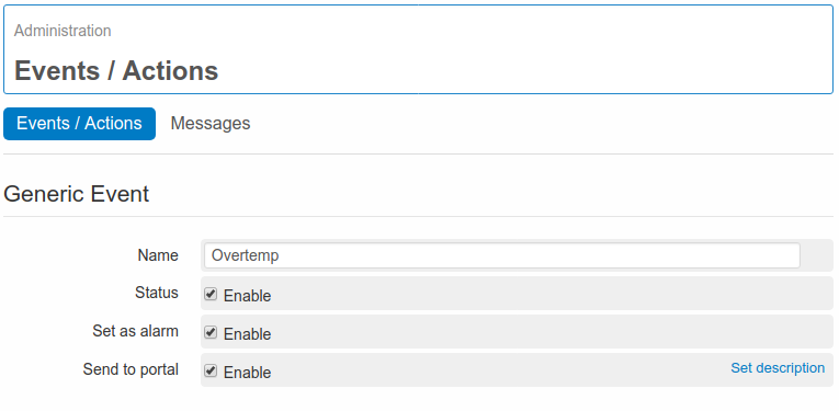
With the option Set as alarm enabled, at the occurrence of the event,, a red ”X” will be displayed near the name of the relevant variable on the page Status → Variables Status status, to indicate the presence of a critical condition.
The Send to Portal option allows to send an event to a web portal. At the occurrence of the event, the WE500 will execute the associated action/s and send to Portal a string containing the name of the event and other additional information.
4.1.1. Event on variable
Event on variable refers to an event that occurs when a variable reaches a defined value or a defined status.
This kind of event is influenced by the behaviour of the variables associated with it.
The Event on variable will be influenced by the delay of the variables in signaling their status and by the time, the variables keep their status.
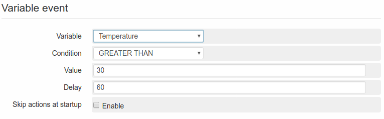
First of all a variable in the field variable has to be selected.
In the drop-down menu is possible to see all previously created variables and select the one to be associated to an event.
The second parameter to be selected is the Condition, among the following possibilities: EQUAL, NOT EQUAL, GREATER THAN, GREATER OR EQUAL THAN, LESS THAN and LESS OR EQUAL THAN.
It’s now necessary to set the threshold value for the event triggering, i.e. a numeric value will be entered in the field Value, according to the type of the selected variable.
It’s possible to set a value in the field Delay. The value is expressed in second, the function of this parameter is to postpone the triggering of the event for a defined time.
Finally it’s also possible to enable the field Skip first event, that allows the WE500 to ignore the first time that an event occurs.
This can be useful, for instance, in case of an analogue variable (with an ever changing value, having a floating mode). Setting a delay it’s possible to avoid the triggering of any event, before the value has come to a stabilized value. If the delay has been for example set at 10 seconds, the value entered in the relevant field will be kept until the expiry of the 10 seconds, allowing the execution of any possible events.
Once set all parameters, the situation may be the following:
Variable: Var1
Condition: EQUAL
Value: 3
Delay:10
According to this configuration the event would be triggered 10 seconds after the variable Var1 has reached the value 3.
4.1.2. Event on event
Once defined an event it’s possible to use it as an element of another event.
The behavior of the Event on event can be different according to the kind of event used to create it.
The Events on variables, depending on the variables they’re associated with, mostly influence the creation of Events on events.
EXAMPLE:
The event “EV1” is configured to occur if the variable “Var1” has value “3”
The event “EV2” is configured to occur if the variable “Var2” has value “5”
We can now define an event “EV3” that will occur if both “EV1” and “EV2” are triggered or if one of them is triggered.
According to the above mentioned example, the events on variable “EV1” and “EV2” may have associated actions or not.
The two will be managed separately by WE500, i.e. if “Var1” reaches value “3”(EV1), defined actions may follow (the same is also for “EV2”).
Creating the new event “EV3” it will be possible to define some additional actions to be executed.
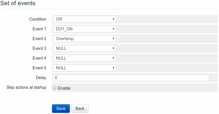
Selecting Events on the field Type, is possible to decide whether to enable or not the event from Status and to display it or not as an alarm in the field Set as alarm.
If this last option is enabled, at the occurrence of the event, a red ”X” will be displayed near the name of the relevant variable on the page Status → Variables Status, to indicate the presence of a critical condition.
The field Condition allows to select the type of comparison that has to be made between one or more events. The two available conditions are AND or OR.
In the fields Events 1…5 is possible to select two or more events among those previously created.
Back to the above mentioned example, and assuming that the selected condition is AND, the event on event “EV3” would be triggered when “Var1” is equal to “3” (of course considering the set delay) and when “Var2” is equal to “5”.
On the other hand, if the selected condition is OR, “EV3” would be triggered even if only one among “EV1” and “EV2” should occur.
All events may be used to generate an event on event.
4.1.3. Event on formula
Event on formula is an event that will occur comparing two maths expressions.
Selecting Formula on the field Type, it’s possible to decide whether to enable or not the event from Status and display it or not as an alarm in the field Set as alarm.
If this last option is enabled, at the occurrence of the event, a red ”X” will be displayed near the name of the relevant variable on the page Status → Variables Status, to indicate the presence of a critical condition.
In the fields Formula can be entered a real maths formula, that may include several arithmetical operations, constants or variables.
The available operations are:
- Addition (+)
- Subtraction (-)
- Multiplication (*)
- Division (/)
- Exponentiation (^)
- Squared root (sqrt)
- Logarithm (log)
- Sine (sin)
- Cosine (cos)
and constants as:
- e(e)
- logarithm base 2 of e (log2e)
- logarithm base 10 of e (log10e)
- square rooted of pi (2_sqrtpi)
- square rooted of 2 (sqrt)
- square rooted of 1/2 (sqrt1_2)
The use of round brackets is also supported.
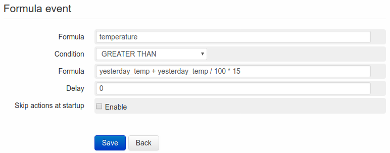
Beside the formula to be compared, it’s also necessary to select a Condition among the following: EQUAL, NOT EQUAL, GREATER THAN, EQUAL OR GREATER THAN, LESS THAN, LESS OR EQUAL THAN.
It’s possible to set a value in the field Delay. The value is expressed in second, the function of this parameter is to postpone the triggering of the event for a defined time.
Finally it’s also possible to enable the field Skip first event, that allows the WE500 to ignore the first time that an event occurs.
Here is an example of event on formula:
Formula: (Var1+5)/2
Condition: EQUAL
Formula: Var2
Delay: 10
The event will be triggered when the result of the formula “(Var1+5)/2” will remain equal to the value of “Var2” for at least 10 seconds.
4.1.4. Incoming data
The incoming data are the events coming from external factors.
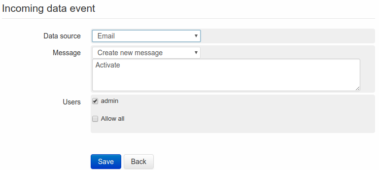
Two are the types of external events managed by the WE500:
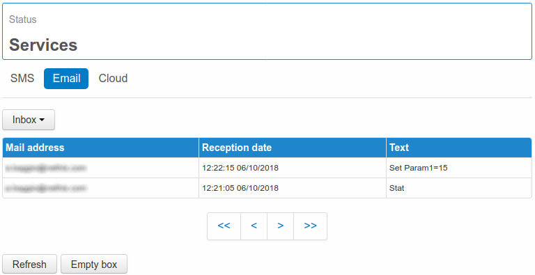
Selecting SMS or Email on the field Data source, it’s possible to enter any text in Message and enable one or more users/groups from the filed Users.
Thus the event will occur when the WE500 receives an SMS or an Email, containing the specified text, sent by an authorized user in Administration –> Users.
Note that the WE500 checks only the object of the mail (relevant commands or instructions must therefore entered in the object and not in the body of the email).
4.2. Actions
Actions allow the WE500 to react to the conditions defined in an event. Through the actions, the WE500 can monitor a system and then send to the users or to other systems the collected data.
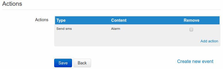
Once created an event and clicked on Save, a new section called Actions will open, where the link Add actions is available.
Clicking on above mentioned link a new page will be entered.
On this page is possible to create an action for the event previously defined. The possible actions are the following: Send Email, Send SMS, Execute a Command, Reboot and Poweroff.
Through the fields Executive action each and Minutes it’s also possible to set, that the action is repeated at regular intervals of time until the event remains activated.
Once created an action, this will be available in the list under the event. It’s possible to create up to 5 actions for each single alarm.
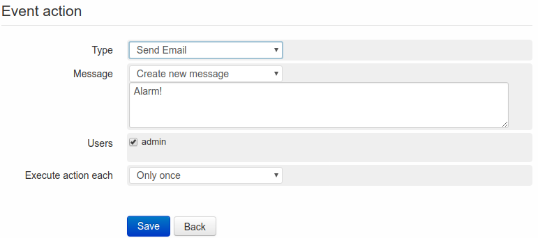
4.2.1. Send Email
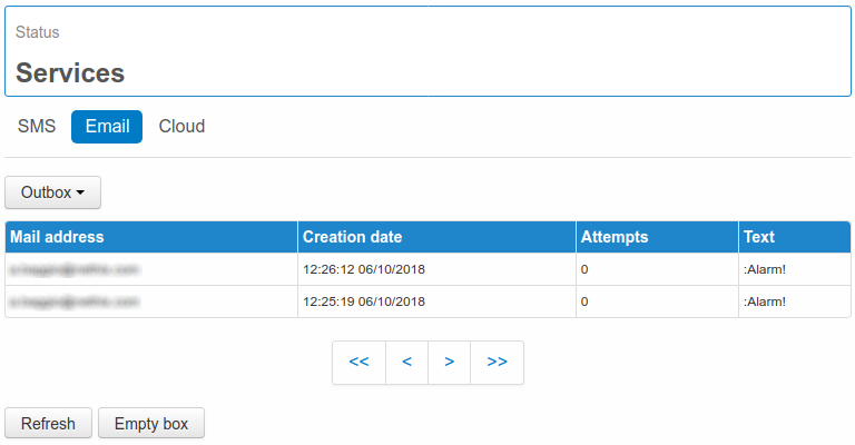
Selecting Send Email, it’s allowed to enter the text to be sent at the occurrence of the event.
If previously used messages are available it’s possible to select them from the field Message, using the drop-down menu.
For entering a new text, select Create new message.
To modify an already existing text, enter the messages page using the link on top of the page or the link in the left side menù Administration –> Events/Actions –> Messages and select the message to be modified.
Once the message is defined, it’s possible to select the receivers among the several available users and groups.
After definition of the event and action that generate the email to be sent to a defined user, some more conditions are necessary:
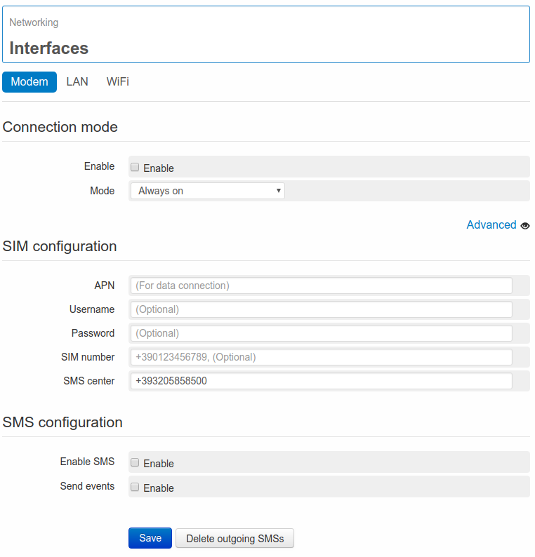
- Availability of a LAN or GPRS/HSPA/LTE connection (see section 10. Connectivity and 12.3. Ping)
- The configured user/s should be enabled to receive notifications emails at a valid email address ( see 9. Users)
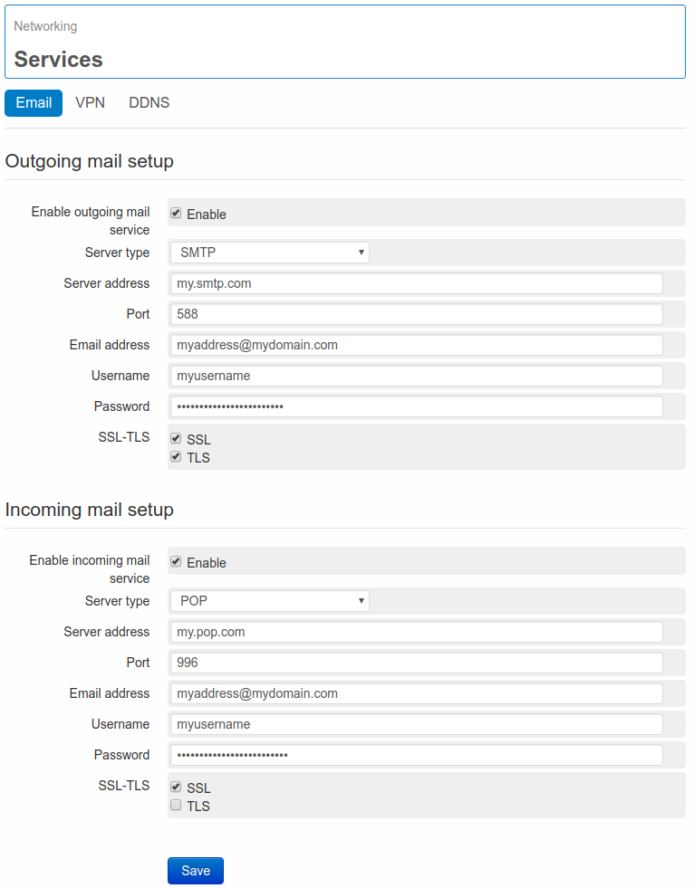
- The mail service must be properly configured (see 10.2.1. Email)
All the text used for the existing actions are available on the page Administration/Event/Actions/Messages. From this page is possible to cancel any message, by clicking on the relevant tab and then Delete, or edit one or more messages by clicking upon it.
On the messages to be sent at the occurrence of defined events, it’s possible to write the value of one or more variables: it’s enough to report on the text of the message $ and the name of the variable.
EXAMPLE
If a variable “VAR1” has value 5.7, and this should be reported in the alarm message, the text of the message should be the following:
Alarm high level. The level is $Var1 meters
The message that will be sent to the configured users will then be:
Alarm high level. The level is 5.7 meters
Inside one single message more variables can be reported.
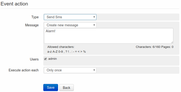
4.2.2. Send SMS
Selecting Send SMS it’s possible to enter the text to be sent at the occurrence of a defined event.
If previously used messages are available it’s possible to select them from the field Message, using the drop-down menu.
For entering a new text, select Create new message.
To modify an already existing text, enter the messages page using the link on top of the page or the link in the left side menù Administration –> Events/Actions –> Messages and select the message to be modified.
Once the message is defined, it’s possible to select the receivers among the several available users and groups.
After definition of the event and action that generate the SMS to be sent to a defined user, some more conditions are necessary:
All the text used for the existing actions are available on the page Administration/Event/Actions/Messages. From this page is possible to cancel any messages, by clicking on Delete, or edit one or more messages by clicking upon it.
On the messages to be sent at the occurrence of defined events, it’s possible to write the value of one or more variables: it’s enough to report on the text of the message $ and the name of the variable.
EXAMPLE:
If a variable “VAR1” has value 5.7, and this should be reported in the alarm message, the text of the message should be the following:
Alarm high level. The level is $Var1 meters
The message that will be sent to the configured users will then be:
Alarm high level. The level is 5.7 meters
Inside one single message more variables can be reported.
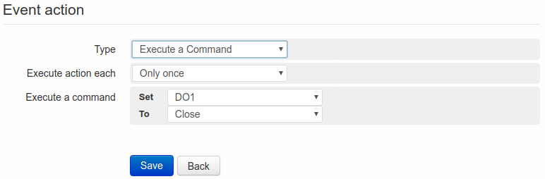
4.2.3. Execute command
Selecting Execute a Command in the field Type is possible to choose a variable among those available in the list below and then specify a value in the filed To.
Thus, at the occurrence of the defined event, the selected variable will be set at the value entered in the field To.
The drop-down menu could miss some of the already created variables. The reason is that the system automatically recognizes the variables, where the value can be modified:
- DO Variables
- Virtual variables
- Modbus write variables
- Modbus write/read variables
For the same reason the following variables will never be included in the menu:
* DI variables
* AI variables
* Modbus read variables
Through an action of Execute a Command, it’s possible to create some automatic operations at the occurrence of a certain event, as for example to close the contact of an output if an analogue input reaches a defined threshold.
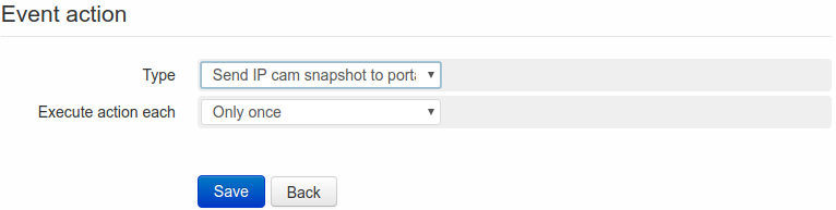
4.2.4. Send IP cam snapshot to portal action
Selecting Send IP cam snapshot to portal from the field Type, it’s possible to send an image, coming from an Ip cam, to a web portal at the occurrence of a certain event.
The IP cam should have been previously configured in proper way on the relevant page (see section 13.2.3. Web-cam).
4.2.5. Reboot action
Selecting Reboot in the field Type, it’s possible to reboot the WE500 at the occurrence of the associated event.
4.2.6. Power off action
Selecting Poweroff in the field Type, the WE500 can be turned off at the occurrence of the associated event
A typical situation where the controlled power-off of the device can be useful, is when the WE500 is battery powered ( for example using a UPS500).
When the battery is low, this could send a request of controlled power-off to the WE500 (through a digital/analogue input), in order to avoid unexpected current interruptions while the system is working.


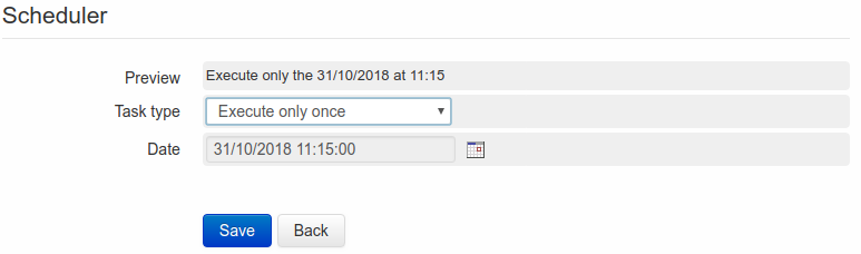
 located on the right side of the field Date, the calender will open and allow to select the hour, the day, the month and the year, when the action has to be executed.
Once the action has been executed, the event will be deleted.
located on the right side of the field Date, the calender will open and allow to select the hour, the day, the month and the year, when the action has to be executed.
Once the action has been executed, the event will be deleted.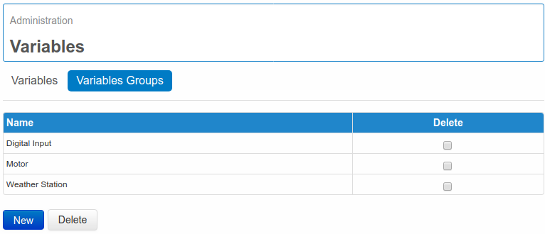
 or gray
  , according to the status and configuration of the variable.
 indicates that no active alarms are available. The icon
  indicates on the other hand the presence of an event configured as an alarm.
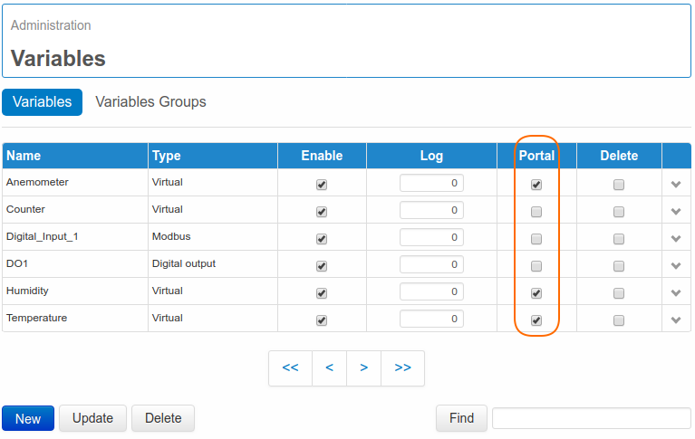

 The product shall not be treated as household waste. It shall be instead handed over to an appropriate collection point for the recycling of electrical and electronic products. For further information about recycling of this product, contact the local city office and/or the local waste disposal service.