XP500/ETH
1. Overview
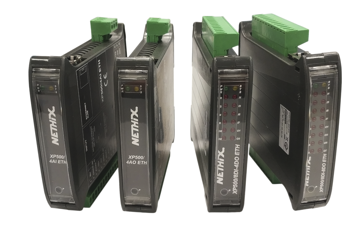
Some applications may require a higher number of inputs and/or outputs as those already available on the WE500 and WE300.
In such a case it’s possible to expand the WE500 and WE300 with additional digital outputs/inputs and analogue outputs/inputs, by adding expansion modules of the XP500/ETH line.
These expanders can be easily installed and configured, following the user-friendly procedure available inside the webinterface of the WE500 and WE300.
Differently from the expanders of the line XP500, these modules communicate with the device through Modbus TCP/IP Protocol, thus they do not require a direct connection to the master device ( WE500/WE300) but only the LAN Network. This allows to cover greater distances without any wiring problems.
All expansion modules are slave type and can be integrated with any Modbus TCP/IP master devices.
2.Technical Features
2.1. 4AI-I/V
The expander 4AI-I/V allows to expand the device with 4 analogue inputs, configurable in current or in tension. The expansion module communicates through Modbus TCP/IP Protocol.
| Description |
Modbus TCP expansion with 4 analogue inputs
in current and tension |
| Analogue Inputs |
- Number of inputs:4
- Min. current: -20mA
- Max. current: +20mA
- Min. tension: -10 V
- Max. tension: +10 V
- Impedance: >= 1M (V) 22 Ohm (mA)
- Sampling time: 150 ms
|
| Communication Protocol |
Modbus TCP/IP Slave |
| Power Supply |
20 / 30 VDC |
| Average consumption |
85 mA @ 24 VDC |
| Protection against rev.polarity |
60 VDC max |
| Insulation |
1500 VAC 50Hz, 1min. |
| Operational Temp. |
-10°C / +60°C |
| Storage Temp. |
-40°C / +85°C |
| Humidity |
0 / 90% (non condensing) |
| Dimensions |
22.5 x 100 x 120 mm |
| Weight |
160 gr |
| Enclosure |
Grey pvc box for DIN rail mount |
| Network interface |
Ethernet 10/100Base-T on RJ45 |
| CE Standards |
EN 61000-6-2, EN 61000-6-4 |
2.2. 4AO
The expander 4AO allows to expand the device with 4 analogue outputs. The expansion module communicates through Modbus TCP/IP Protocol.
| Description |
TCP Modbus Expansion with 4 analogue outputs
in current and in tension |
| Analogue Outputs |
- Number of outputs: 4
- Min. Current : 0 mA
- Max. Current: +20 mA
- Min. Tension: 0 V
- Max. Tension: +10 V
- Load resistance (mA): >= 500 Ohm
- Load resistance (V): >= 5000 Ohm
- Sampling time: 50 ms
|
| Communication protocol |
Modbus TCP/IP Slave |
| Power Supply |
18 / 30 VDC |
| Average consumption |
90 mA @ 24 VDC |
| Protection against rev.polarity |
60 VDC max |
| Insulation |
1500 VAC 50Hz, 1min. |
| Operational Temp. |
-10°C / +60°C |
| Storage temp. |
-40°C / +85°C |
| Humidity |
0 / 90% (non condensing) |
| Dimensions |
22.5 x 100 x 120 mm |
| Weight |
160 gr |
| Enclosure |
Grey pvc box for DIN rail mount |
| Network Interface |
Ethernet 10/100Base-T on RJ45 |
| CE Standard |
EN 61000-6-2, EN 61000-6-4 |
2.3. 8DI-4DO
The expander 8DI-4DO allows to expand the device with 8 digital inputs and 4 digital outputs. The expansion module communicates through Modbus TCP/IP Protocol.
| Description |
TCP Modbus Expansion with 8 digital inputs
and 4 digital outputs |
| Digital inputs |
- Number of inputs: 8
- Status OFF: 0 - 3 V
- Status ON: 10 - 30 V
- Impedance: 4.7 KOhm
|
| Digital outputs |
- Number of outputs: 4 SPDT relays
|
- Min. Load: 5 VDC, 10 mA
- Max. tension: 250 Vca (50 / 60 Hz), 110 VDC
|
| Commutable power (max) |
2A @ 250 Vca by contact |
| 2A @ 30 VDC by contact |
| Communication Protocol |
Modbus TCP/IP Slave |
| Power Supply |
10 / 30 VDC |
| Average consumption |
60 mA @ 24 VDC |
| Protection against rev.polarity |
60 VDC max |
| Insulation |
1500 VAC 50Hz, 1min. |
| Operational temp. |
-10°C / +60°C |
| Storage temp. |
-40°C / +85°C |
| Humidity |
0 / 90% (non condensante) |
| Dimensions |
22.5 x 100 x 120 mm |
| Weight |
190 gr |
| Enclosure |
Grey pvc box for DIN rail mount |
| Network Interface |
Ethernet 10/100Base-T on RJ45 |
| CE Standard |
EN 61000-6-2, EN 61000-6-4 |
2.4. 8DI-8DO
The expander 8DI-8DO allows to expand the device with 8 digital inputs and 8 digital outputs. The expansion module communicates through Modbus TCP/IP Protocol.
| Description |
Modbus Expansion with 8 digital inputs and 8
digital outputs |
| Digital inputs |
- Number of inputs: 8
- Status OFF: 0 - 3 V
- Status ON: 10 - 30 V
- Impedance: 4.7 KOhm
|
| Digital outputs |
- Outputs: 8 PNP
- Inductive load: 48 Ohm - 2H max
- Tension: 10.5/30 VDC
|
| Max Load |
500 mA each output |
| 1 A each module |
| Communication Protocol |
Modbus TCP/IP Slave |
| Power Supply |
10 / 30 VDC |
| Average consumption |
60 mA @ 24 VDC |
| Protection against rev.polarity |
60 VDC max |
| Insulation |
1500 VAC 50Hz, 1min. |
| Operational Temp. |
-10°C / +60°C |
| Storage Temp. |
-40°C / +85°C |
| Humidity |
0 / 90% (non condensing) |
| Dimensions |
22.5 x 100 x 120 mm |
| Weight |
160 gr |
| Enclosure |
Grey pvc box for DIN rail mount |
| Network Interface |
Ethernet 10/100Base-T on RJ45 |
| CE Standard |
EN 61000-6-2, EN 61000-6-4 |
3. Web Interface
All types of XP500/ETH include a web server, that can be reached by digiting the relevant IP Address on the browser address bar.
Once entered the interface, digiting Username and Password, it’s possible to display or modify some configuration parameters.
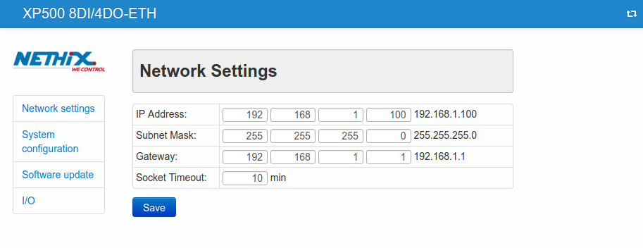
The default network configuration for the connection of the XP500/ETH is:
- IP address: 192.168.1.100
- Netmask: 255.255.255.0
- Gateway: 192.168.1.1
The PC, used for connecting to the XP500/ETH, must be available inside the 192.168.1.x network. After the first access, it’s possible to change the network settings and assign the desired IP.
To connect to the the web interface of the XP500/ETH it’s enough to digit the following address on a standard web browser (Google Chrome and Mozilla Firefox are recommended):
192.168.1.100
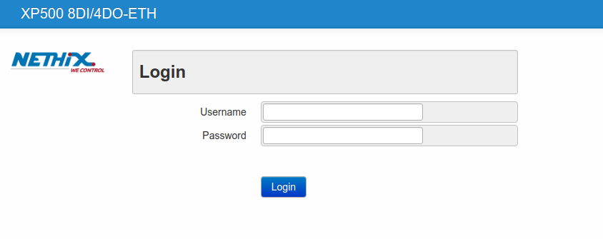
Once entered the login page, the access credentials are required. The default username and password are the following:
- Username: admin
- Password: admin
Once entered the login page of any type of XP500/ETH, the first page dispayed is “Network Settings”. Using the menu available on the left side of the web interface, it’s possible to select one of the following items:
- Network settings
- System configuration
- Software update
- I/O
3.1. Network settings
On this page the network configuration of the XP500/ETH expansions can be changed.
Once changed the IP Address and clicked on Save, the expansion unit will reboot automatically (about 2 seconds time) and the page will be reloaded on the new IP Address.
Hint
It’s highly recommended to change the IP Address in order to keep the IP 192.168.1.100 reserved for the configuration of possible further XP500/ETH.
3.2. System configuration
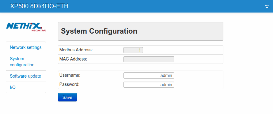
On the page System configuration it’s possible to visualize the Modbus address, the MAC Address and the access data Username and Password.
The MAC Address is a unique address assigned to the devices and cannot be changed. The Modbus address represents the Modbus address of the expansion units and can be modified only through the configuration procedure from the master device (WE300/WE500).
Username and Password can be modified by the user.
Hint
For safety reason it’s always recommended to change the access data Username and Password.
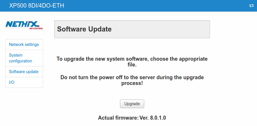
3.3. Software update
If required, from the page Software update it’s possible to start the software update procedure for the expansion units. The currently available software version is visualized.
After clicking on Upgrade it’s possible to enter the page, where the file can be loeaded to start the installation.
Once clicked on Upload the device will start the installation, that might take few seconds.
After the installation a white page with two links will appear:
Click on Reboot. On the activated expansion unit the yellow led STS will light on for a few seconds. When the led lights off it’s possible to return to the menu.
In order to check that the installation has been properly executed, select once again the page Software update from the menu and check if the version number has been updated.
Warning
During the update procedure don’t switch off the device for any reason.
3.4. I/O
Differently from all other pages on the menu, the I/O page changes according to the specific type of XP500/ETH considered.
3.4.1. 4AI
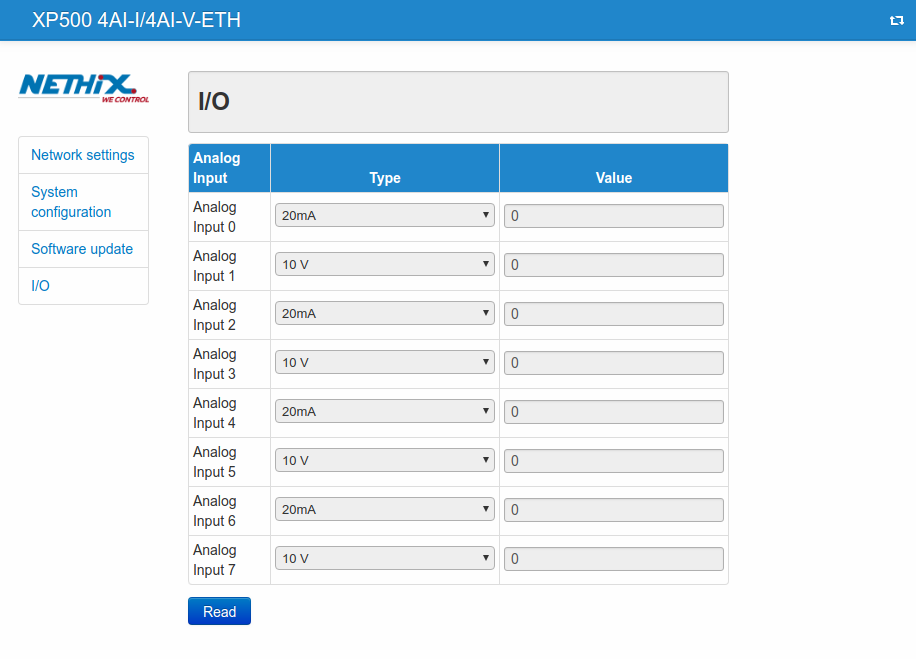
The expansion XP500/ETH-4AI allows to read 4 analogue inputs, both in current and in tension.
On the I/O page the values read by the expansion on each channel will be displayed.
It will be possible to update the values available on the column Value clicking on Read.
3.4.2. 4AO
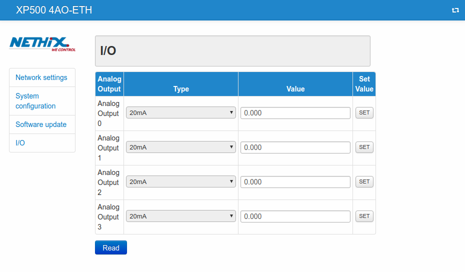
The expansion module XP500/ETH-4AO allows to manage 4 analogue outputs, in current or tension.
On the I/O page it’s possible to control directly the analogue outputs. It’s required to digit a valid value on the field Value (between 0 and 20 if the output is configured in mA, between 0 and 10 if the output is in V), then to click on button SET, available near the desired channel.
It’s possible to update the values indicated on the column Value clicking on Read.
On the other hand it’s not possible to change the configuration of the analogue outputs (current or tension).
Warning
XP500/ETH-4AO allows to choose between analogue outputs in tension and analogue outputs in current. Each configuration is independent (it’s also possible to have mixed configurations). The selection of the type of analogue output is made through the interface of the master device (WE500 o WE300).
3.4.3. 8DI4DO
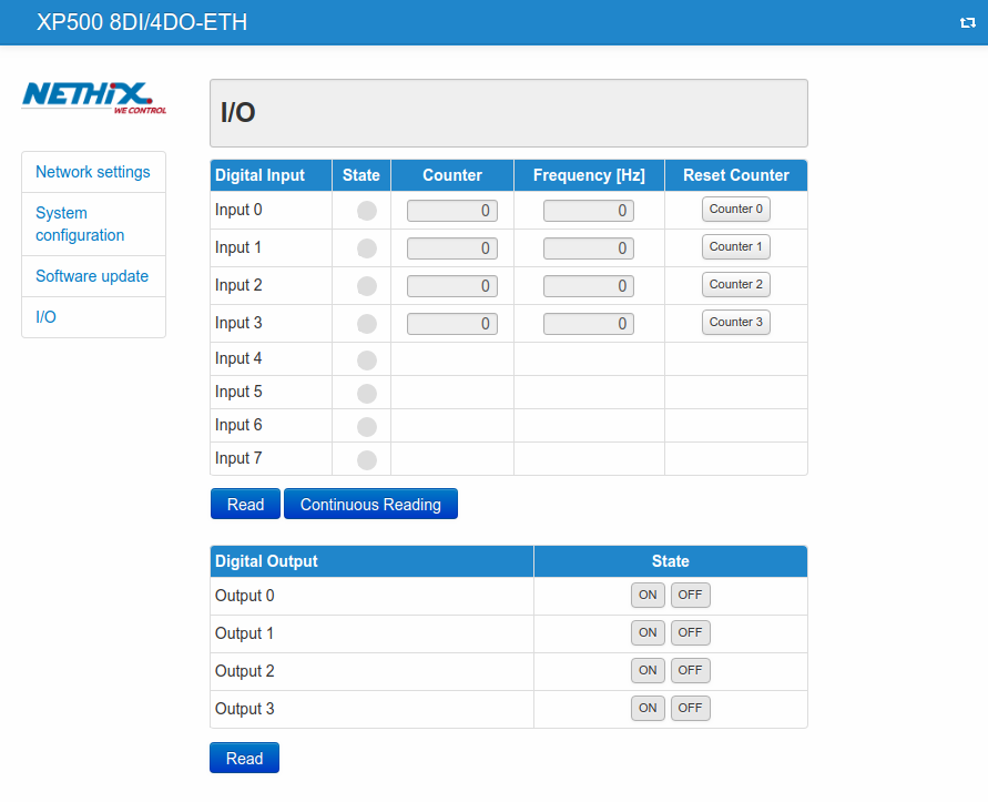
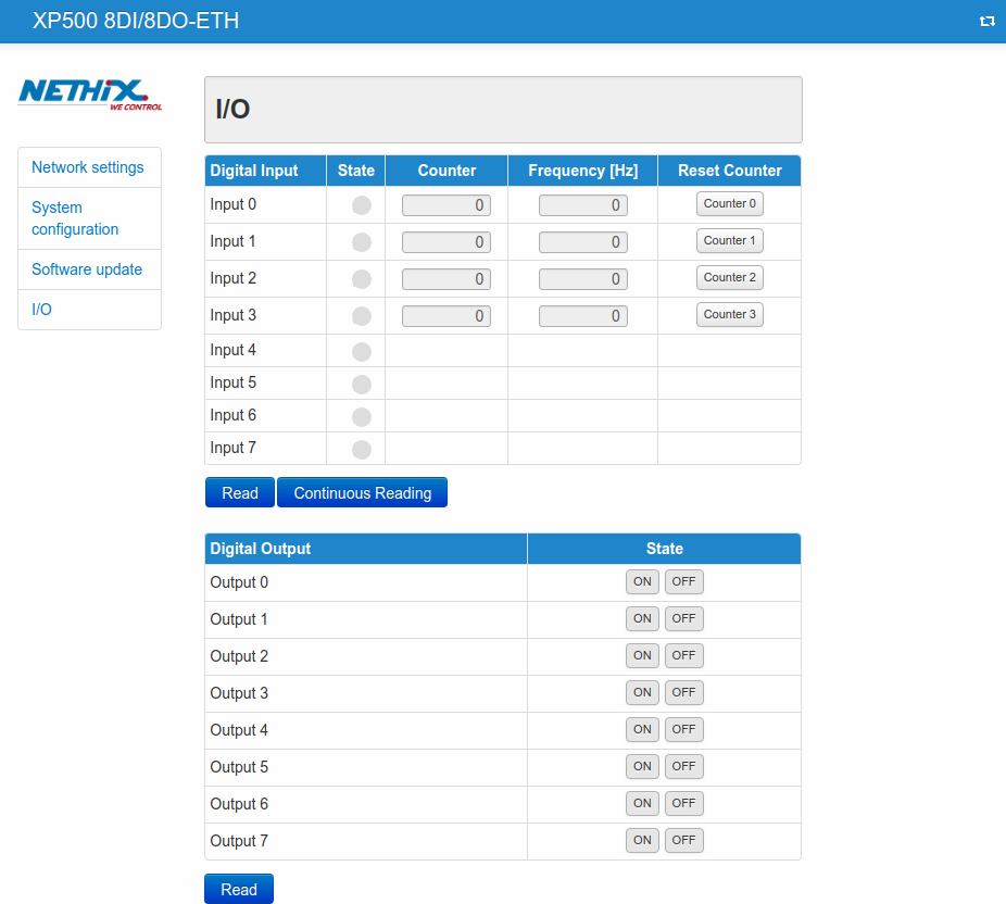
The expansion module XP500/ETH-8DI4DO allows to control 4 relay outputs and read the status of 8 digital inputs.
On the first section the status of the 8 digital inputs will be displayed:
- State: reports the input status through an indicator. The grey indicator means “open” input, when the indicator is green the input is “closed”.
- Counter: reports how many times the inputs has been closed.
- Frequency: reports the frequency (in HZ) of the contact closing. The frequency is calculated considering the time between two closings
- Reset Counter: clicking on this, it’s possible to reset the counter value, displayed on the field Counter
The button Read allows to update the inputs status, clicking on Continuous Reading the status of the inputs will be automatically updated once every second.
On the second section the status of the 4 relay digital outputs is displayed. On the column State it’s possible to click on ON and OFF in order to close or open the relay contact (when the contact is closed the button ON is green).
Clicking on Read it’s possible to read the updated status of the outputs.
3.4.4. 8DI8DO
The expansion module XP500/ETH-8DI8DO allows to manage 8 digital outputs (transistor) and read the status of the 8 digital inputs.
On the first section the status of the 8 digital inputs are displayed:
- State: reports the input status through an indicator. The grey indicator means “open” input, when the indicator is green the input is “closed”
- Counter: reports how many times the input has been closed
- Frequency: reports the frequency (in Hz) of the contact closing. The frequency is calculated considering the time between two contact closings.
- Reset Counter: clicking on this, it’s possible to reset the counter value, displayed on the field Counter
The button Read allows to update the inputs status, clicking on Continuous Reading the status of the inputs will be automatically updated once every second.
On the second section the status of the 8 digital outputs is displayed. On the column State it’s possible to click on ON and OFF in order to close or open the relay contact (when the contact is closed the button ON is green).
Clicking on Read it’s possible to read the updated status of the outputs.
4. Configuration
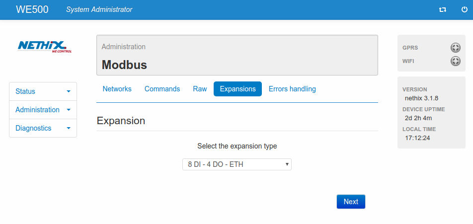
Using the Web interface of WE500 and WE300, inside section 3.6. Modbus expansions, it’s possible to install one or more expansions with a quick procedure, just following the installation wizard instructions:
- Go to page Administration -> Modbus -> Expansions of WE500 or WE300
- Click on New
- It’s now required to choose the desired expansion type. The available types of XP500/ETH are the following:
- 4 AI - ETH
- 4 AO - ETH
- 8 DI - 4 DO - ETH
- 8 DI - 8 DO - ETH
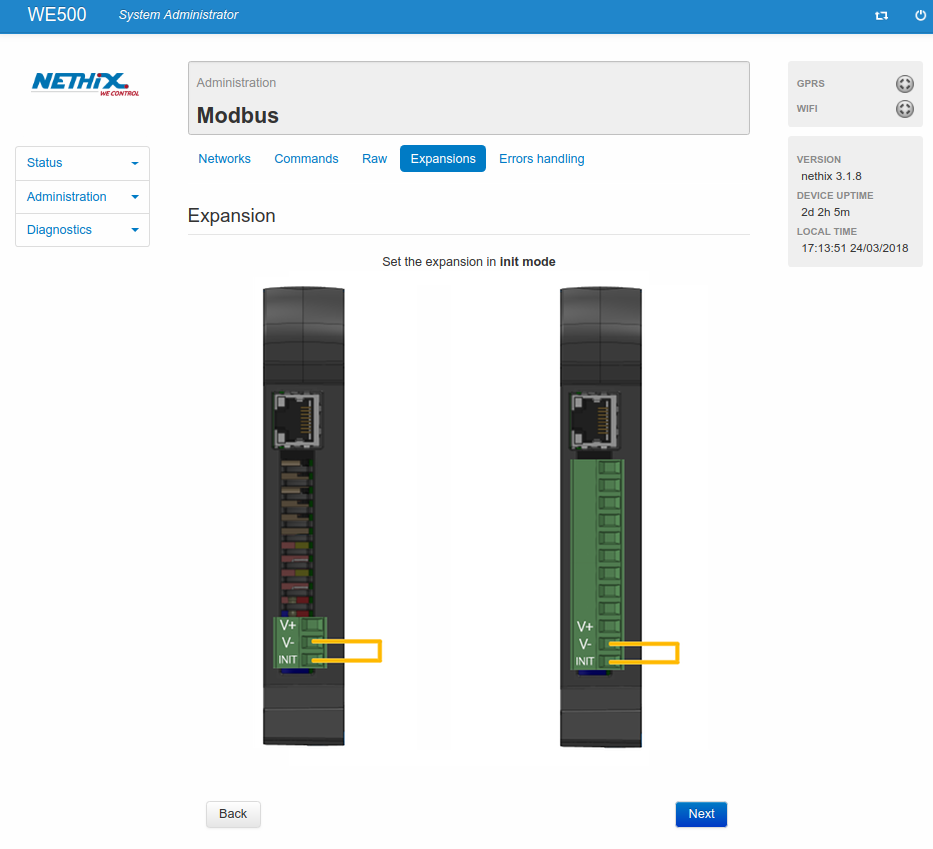
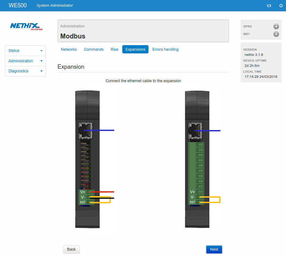
- After the selection of the expansion type and having clicked on Next, it’s then required to switch the expansion into INIT Mode (see paragraph 5. Reset to factory settings)
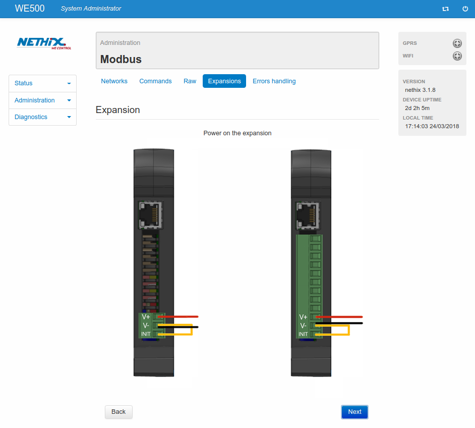
- Once the bridge with switched off device is made, click on Next. It’s now required to power the expansion unit.
- Once powered the device and clicked on Next, it’s required to connect the Ethernet cable to the RJ45 connector of the XP500/ETH.
Hint
In INIT mode the expansion unit takes the address IP 192.168.1.100 regardless of the previous settings.
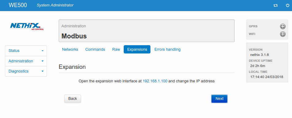
7. Connect the cable and click on Next. It’s now required to connect to the interface of the XP500/ETH, by clicking on the reported link or writing the address 192.168.1.100 on
the address bar of the browser. It’s important to make sure that the PC in use for the configuration is inside the same network of the XP500/ETH. In case it couldn’t be possible to connect to the IP address 192.168.1.100, check and correct the network settings of the PC (setting for instance the address IP 192.168.1.50).
- Change the IP from the page Network Settings, after the login on the web interface of the XP500/ETH
Hint
Even after the IP address change, the expansion module will still be available at the previous address 192.168.1.100 until the INIT mode won’t be abandoned.
- AFter changing the IP of the XP500/ETH and having clicked on Save, return to the interface of the master device (WE500 o WE300) and click Next
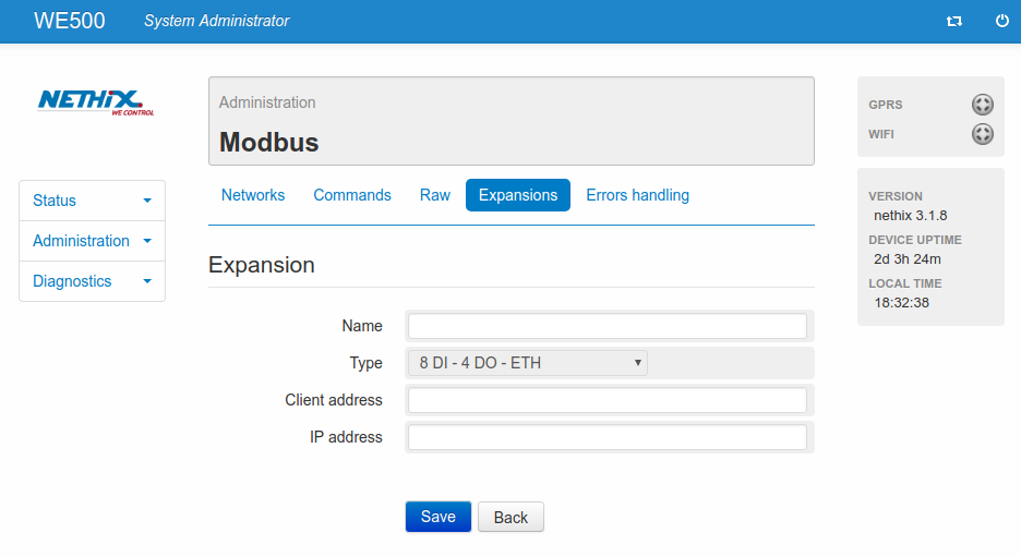
- It’s now required to assign a name to the XP500/ETH, a Modbus address and the IP address:
- Name: it’s possible to assign a name to the XP500/ETH in order to make the identification simpler
- Modbus address: it’s possible to set a Modbus address for the XP500/ETH. The parameter is not relevant, since the TC/IP communication won’t consider it. It’s enough to enter a value between 1 and 247.
- IP address: in this field must be entered the IP Address of the XP500/ETH, that has to be added. The IP must be the same as the one set in the expansion under point 8.
Only in the case of the configuration of a XP500/ETH-4AO, it will also be required to specify the type of analogue output, choosing for each channel between 0-20mA and 0-10V.
Once clicked on Save the master device will try to communicate with XP500/ETH, if the procedure is correct, the Modbus TCP/IP network, the commands and the variables associated with the I/O of the relevant XP500/ETH will be created.
Hint
The commands and the Modbus networks created through the automatic procedure cannot be modified, on the other hand it’s possible to modify some variables parameters such as: Name, Scaled Minimum value e Scaled Maximum value. For further information about the meaning of such parameters see the manual of the master device (WE500 o WE300).
Warning
For the use of XP500 in combination with other devices, other than WE500 and WE300, you’re requested to get in contact with Nethix.
5. Reset to factory settings
If a reset to factory settings of the XP500/ETH is required, or if the credentials or network settings have been lost, there are two possible reset procedures, that might restore the device to a known state:
- Mode INIT
- Front button reset
5.1. Mode INIT
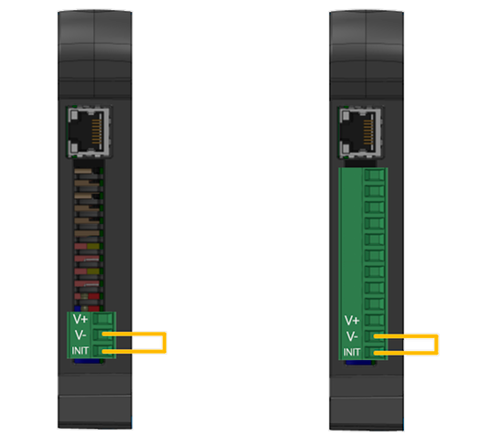
The mode INIT allows to recover the device to a known state, in order to connect through the web to its interface and change the network parameters and access data.
For entering the INIT mode, follow the steps below described:
- Turn off the XP500/ETH
- Connect the terminal INIT to the terminal -VS as per following picture ( building a bridge through an electrical wire)
- Turn on the device
- Connect to the device interface using the following parameters:
- IP address: 192.168.1.100
- Username: admin
- Password: admin
- Indirizzo Modbus: 245
It’s now possible to modify the network parameters and the access credentials. Note that the modifications made ( for example the IP address modification) will be applied ony after quitting the INIT Mode.
To quit the INIT Mode follow the procedure below:
- Switch off the device XP500/ETH
- Remove the bridge available between the terminals INIT and -VS
- Switch on the device XP500/ETH
6. Warnings
- This device is not suitable to be installed by non technical personnel.
- Nethix is not responsible in case of improper use of the devices and for the consequences that this improper use may cause.
- Nethix products are suitable to be used in common applications in the fields of industrial or home automation, remote controlo, remote assistance and management, telemetry, etc. Those who intend to use Nethix products on special applications, where possible failures or malfunctions may have direct effects on human life or cause phyisical or material damages, or where the highest level of reliability is required (such as aerospace systems, control-systems for atomic energy, electromedical devices, etc.) are requested to contact Nethix. Nethix is not responsible for damages caused by such uses if not previously authorized.
 he product shall not be treated as household waste. It shall be instead handed over to an appropriate collection point for the recycling of electrical and electronic products. For further information about recycling of this product, contact the local city office and/or the local waste disposal service.
7. Warranty and assistance
Nethix grants to the buyer that the product will be free of material and production defects for a time period of 2 years (24 months) from the purchase date.
During the warranty period, against presentation of the proof of purchase, the product will be repaired or substituted at Nethix’s discretion, without any costs for spare parts or repair works.
Warranty is invalidated in case of improper use or misuse.
In case of technical problems the buyer may ask for technical assistance at Nethix in one of the following ways:
- Contacting his own reseller or distributor
- Sending an e-mail to the following address support@nethix.com
8. Return and repairs
The return of goods for repair or substitution must previously be authorized by the technical staff at Nethix, requesting an official RMA number.
An e-mail containing the following information shall be sent to Nethix or to the supplier:
- Company Name or customer data (address, tel, fax, email)
- Contact person
- Place of purchase
- Product data, P/N and S/N available on the backside of each device or on the original packaging
- Detailed description of the defect
Nethix will promptly send the RMA number and the customer shall then arrange the return of the goods for repair.
All goods must be sent free Nethix factory, without transport costs at Nethix charge.
Material delivered without factory seals shall be automatically considered outside warranty terms.




 he product shall not be treated as household waste. It shall be instead handed over to an appropriate collection point for the recycling of electrical and electronic products. For further information about recycling of this product, contact the local city office and/or the local waste disposal service.