JSON Configuration file

../_images/tp100.png

1. Overview

The recommended method to configure TP100 is by using the Configuration Wizard available online at the following link.

However, there is also the possibility to manually edit the configuration file using a standard browser.
The properly formatted configuration file (using the JSON format) can be obtained from the online configurator mentioned above (see chapter 5. Upload/Download - Downloading and Uploading Configuration of the respective manual), or by connecting TP100 to your PC, as described in the user manual (9. Downloading Configuration).
Below are the guidelines that must be followed when editing the configuration file and the description of all fields for each Modbus register/variable.

2. Formatting

TP100 recognizes only a properly formatted JSON file as a valid configuration file, containing all expected fields (which will be described later).
The configuration of each Modbus register/variable consists of a predefined set of parameters.
Considering that TP100 supports a maximum of 20 registers/variables, the configuration file will consist of 20 sets of parameters.
To obtain a valid JSON file, it is important to include the following:
  • The first line of the file must start with the character [
  • The last line of the file must end with the character ]
  • Each set of parameters (each Modbus register/variable) should be enclosed within curly braces { and }
  • Between a closing curly brace and an opening one, include a comma ,. Do not add a comma after the 20th (last) set, just before the closing square bracket.
  • Each parameter should be enclosed in double quotes (), followed by the parameter value preceded by a colon : and a space
  • After specifying the value/string for the parameter, add a comma , to separate it from the next parameter
  • Do not add a comma after the last parameter (just before the closing braces)
  • Even if the number of registers to read is less, it is advisable to include all 20 sets of parameters, leaving default values for those not used (or specifying 0 in the Enable field)
For simplicity, here is an example with only 2 variables/registers, which still demonstrates how to open/close the file and separate sets:
[
 {
     "id": 1,
     "enable": 1,
     "name": "First_register",
     "unit": "V",
     "modbusType": 2,
     "modbusAdr": 1,
     "modbusRegister": 0,
     "modbusCmdRead": 3,
     "modbusCmdWrite": 6,
     "bitPosition": 0,
     "viewMin": 0,
     "viewMax": 0,
     "min": 0,
     "max": 0,
     "decimalNum": 0,
     "readOnly": 0,
     "alarm": 0,
     "thresholdAlarm": 0,
     "passwd": ""
 },
 {
     "id": 20,
     "enable": 1,
     "name": "Last_register",
     "unit": "mA",
     "modbusType": 2,
     "modbusAdr": 1,
     "modbusRegister": 19,
     "modbusCmdRead": 3,
     "modbusCmdWrite": 6,
     "bitPosition": 0,
     "viewMin": 0,
     "viewMax": 0,
     "min": 0,
     "max": 0,
     "decimalNum": 0,
     "readOnly": 0,
     "alarm": 0,
     "thresholdAlarm": 0,
     "passwd": ""
 }
]

There are several websites/tools available online to verify the correct formatting of a JSON file. However, the quickest method to obtain one compatible with TP100 is by connecting the device to your PC or by using the Configuration Wizard.


3. Arrangement of Tiles

Each set of parameters corresponds to a register/variable and therefore to a tile that will be displayed on the screen.
It is possible to establish the order of the tiles also by manually editing the configuration file, using the id parameter.
This parameter can be assigned a value between 1 and 20. Any number outside this range will be considered invalid.
It is not necessary to list the id values in ascending order, although it is recommended for better future readability.
The id values must be unique; the same id cannot be used twice.
TP100 will always attempt to add a new tile to the right of the previous one.
If this is not possible (for example, if there is not enough space in the row), the new tile will be added to the left of the next row.

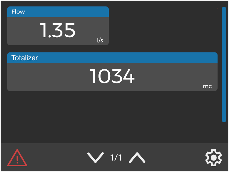
EXAMPLE

  • “id”: 1 corresponds to a half variable (thus occupying half a row) called Flow.
  • “id”: 2 corresponds to a full variable (thus occupying a whole row) called Totalizer.
The second tile will not be displayed in the first row because there would not be enough space available.
The result will be as shown in the following image:
../_images/order.png

Any additional third variable (with “id”: 3) would be displayed on the third row, following the Totalizer variable.


4. Parameters Description

Below is the description of the parameters for each set, necessary to define the configuration of each individual Modbus register/variable.
  • “id”: From 1 to 20. Specifies the order in which to display the registers.
  • “enable”: Set to 0 disables the register (its tile will not be displayed), set to 1 enables it.
  • “name”: Allows specifying the name to be assigned to the register, with a maximum of 31 characters. Alphanumeric characters, spaces, and _ (underscore) are allowed.
  • “unit”: Unit of measurement for the variable, with a maximum of 9 characters. Alphanumeric characters, spaces, and _ (underscore) are allowed. It can be left empty (use “” instead of a value).
  • “modbusType”: Selects the Modbus variable type (number of bits). This parameter directly affects the size of the tile. See section 4.1. modbusType for more information.
  • “modbusAdr”: Sets the Modbus address of the device from which to retrieve values. According to the Modbus protocol specification, a value between 1 and 255 can be entered.
  • “modbusRegister”: Specifies the Modbus register from which to retrieve values. Values within the range 0 - 65535 are allowed.
  • “modbusCmdRead”: Specifies the Modbus function code to be used to access the register specified in the modbusRegister field. It should be selected based on the information provided in the manual of the device that TP100 will interface with. The mapping between the values that can be assigned to this parameter and the respective Modbus function is available in section 4.2. Parameter: modbusCmdRead.
  • “modbusCmdWrite”: Specifies the Modbus function code to be used to modify the value of the register specified in the modbusRegister field via touch display. This parameter is considered only if readOnly is set to 0. It can be set to 0 if there is no need to modify the register value from the display. The mapping between the values that can be assigned to this parameter and the respective Modbus function is available in section 4.3. Parameter: modbusCmdWrite.
  • “bitPosition”: Specifies the bit to associate the variable with, useful only in the case of 1-bit and 8-bit variables. For the former, a value between 0 and 15 can be specified (where 0 represents the least significant bit), while for the latter, the values 0 (least significant byte) or 8 (most significant byte) can be specified. If the variable being defined is 16 or 32 bits, this parameter will be ignored (in this case, it is advisable to set it to 0).
  • “viewMin”: Together with viewMax, it scales the read value within the desired range. The minimum value that can be entered is -2147483648. It can be left as 0 (along with viewMax) if no scaling is intended.
  • “viewMax”: Together with viewMin, it scales the read value within the desired range. The maximum value that can be entered is 2147483648. It can be left as 0 (along with viewMin) if no scaling is intended.
  • “min”: Allows adding additional scaling to the read value, if the Modbus device connected to TP100 returns a non-standard range. It is recommended to set this field to 0 as it is not necessary in most cases.
  • “max”: Allows adding additional scaling to the read value, if the Modbus device connected to TP100 returns a non-standard range. It is recommended to set this field to 0 as it is not necessary in most cases.
  • “decimalNum”: Number of decimal places to display in the read value. A value between 0 and 4 can be specified. In the case of 1-bit variables, this parameter is ignored (although it is recommended to set it to 0).
  • “readOnly”: Set to 1 it makes the variable read-only; the value of the register cannot be modified from the display. Set to 0 it allows using the function specified in the modbusCmdWrite field to modify the value.
  • “alarm”: Selects the alarm condition to be applied to the threshold specified in the thresholdAlarm field. Once triggered, it will change the color of the associated tile to red. Set to 0 if no alarm condition is to be defined; in that case, the value specified in the thresholdAlarm field will be ignored. All other selectable values will be described in section 4.3. Parameter: alarm.
  • “thresholdAlarm”: Defines the value of the alarm threshold. Depending on the condition specified in the alarm field, when the register enters an alarm state, the upper border of the tile will be highlighted in red. The specified value must fall within the range defined by the viewMin and viewMax fields.
  • “passwd”: Sets a numerical code to be entered if you intend to modify the value of the Modbus register. The code can be between 3 and 6 digits long. If a value other than 0 has been assigned to readOnly, the parameter will not be considered. If no numerical code is to be defined, leave the field empty (enter “” instead of a value).

4.1. modbusType

In the modbusType field, values in the range 0-9 can be entered. Each value corresponds to a specific type of Modbus variable.
The table below also lists the minimum and maximum values expected for each variable type. If viewMin and viewMax parameters are left at 0, the range below will be used without any scaling applied.
Value to Enter Variable Type Tile Size Minimum Maximum
0 1bit - Boolean Half (half row) 0 1
1 8bit - Byte Half (half row) 0 255
2 16bit - Half signed Half (half row) -32768 32767
3 16bit - Half unsigned Half (half row) 0 65535
4 32bit - Int signed Full (full row) -2147483648 2147483648
5 32bit - Int unsigned Full (full row) 0 4294967295
6 32bit - Int signed inv Full (full row) -2147483648 2147483648
7 32bit - Int unsigned inv Full (full row) 0 4294967295
8 32bit - Float Full (full row) 0 4294967295
9 32bit - Float inv Full (full row) 0 4294967295

Further information about each variable type can be found in the dedicated chapter of the online configurator manual (3.2. Variable Type).

4.2. Parameter: modbusCmdRead

In the modbusCmdRead field, you can enter values corresponding to the decimal code of the Modbus read function to be used for accessing the register:

Value to Enter Modbus Function
1 0x01 - Read Coil Status
2 0x02 - Read Input Status
3 0x03 - Read Holding Registers
4 0x04 - Read Input Registers

Further information about each read function can be found in the dedicated chapter of the online configurator manual (3.1.1. Read Functions).

4.3. Parameter: modbusCmdWrite

In the modbusCmdWrite field, you can enter values corresponding to the decimal code of the Modbus write function to be used for modifying the value of a register:

Value to Enter Modbus Function
5 0x05 - Force Single Coil
6 0x06 - Preset Single Register
15 0x15 - Force Multiple Coils
16 0x16 - Preset Multiple Registers

Further information about each write function can be found in the dedicated chapter of the online configurator manual (3.1.2. Write Functions).

4.3. Parameter: alarm

In the alarm field, you can enter values corresponding to the type of alarm condition to be defined, with reference to the threshold entered in the thresholdAlarm field.
Below is the correspondence between the numerical value to be entered and the alarm condition:
Value to Enter Alarm Condition
0 No alarm
1 Alarm if equal to thresholdAlarm
2 Alarm if less than thresholdAlarm
3 Alarm if greater than thresholdAlarm