User manual

../_images/tp100.png

1. Overview

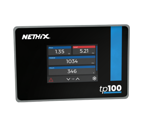
TP100 is a programmable touch screen display capable of communicating via Modbus RTU over RS485 and RS232.
Although it is designed for the Nethix product range, it is compatible with any Modbus RTU server device.
It supports reading up to 20 Modbus registers, with read data displayed on the screen in the order defined by the user (see Configuration Wizard).
This manual provides detailed information on all features of TP100 available in version V00B000 (07/2024).
Please ensure that the firmware version of TP100 matches this manual, as some features may vary between versions.
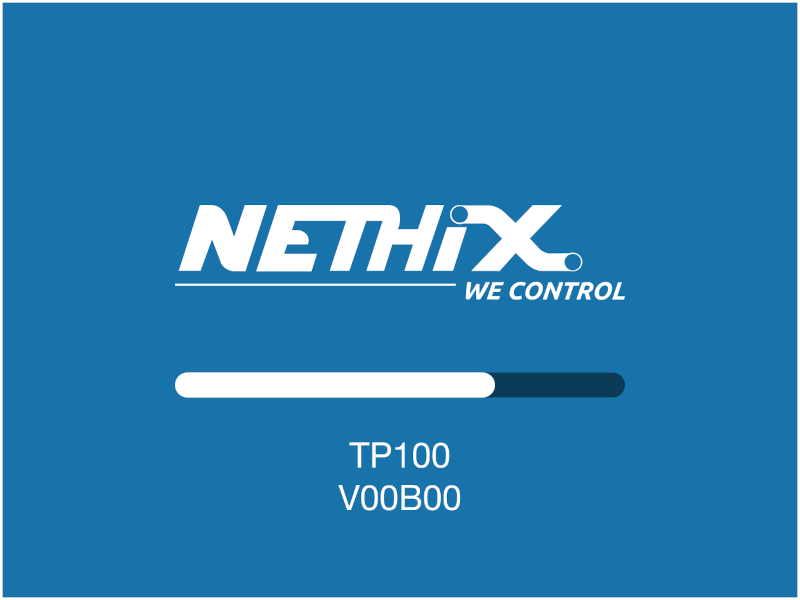
The firmware version is displayed on the startup screen immediately after powering on the device.
If this manual does not adequately cover a particular topic, please contact Nethix technical support for further information.

2. Startup and Home Screen

For information on powering up the device and making the necessary connections to make it operational, please refer to the relevant manual: Hardware manual.
Once the device is powered on, the initial loading screen will appear on the display:
../_images/boot_screen.png
From this initial screen, you can verify the device’s firmware version.
Once the loading bar is complete, the device will display the main screen (home screen):
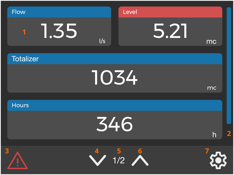
../_images/home_screen.png
  • 1 The tiles are the main elements of the home screen. More information can be found in section 3. Tile Description.
  • 2 The sidebar (if multiple pages are present) allows scrolling through the displayed elements.
  • 3 The alarm icon is displayed if TP100 is experiencing communication issues with at least one Modbus register.
  • 4-6 The navigation arrows allow you to move between the various pages on the display, enabling you to view all available tiles.
  • 5 Current page indicator (number on the left) on the total number of pages (number on the right).
  • 7 Tapping this icon it opens the settings menu. More information is available inside the dedicated section (6. Settings Menu).
The display area for viewing register values is organized into a matrix of 3 rows and 2 columns.
Therefore, a maximum of 6 variables/registers can be displayed per page, depending on the tile size (more information on tile sizes can be found here: Configuration wizard).
There is no limit to the number of pages; however, a maximum of 20 tiles/registers can be displayed in total.
In addition to the navigation arrows and the sidebar, the displayed elements can also be scrolled by dragging any area of the display up or down.

Note

If TP100 has never been configured before, the home screen will be empty, showing only the navigation buttons and the settings menu.


3. Tile Description

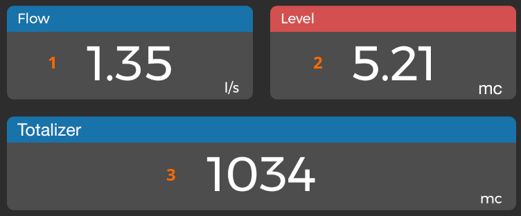
The tiles are the main elements of the home screen and represent the area where the read register values will be displayed.
The order in which the tiles are displayed is set during the configuration phase; for more information, refer to the Configuration Wizard.
Up to 20 tiles can be displayed, organized into multiple pages, corresponding to 20 registers/variables to be read.
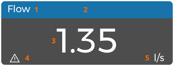
../_images/tile_full.png
In addition to the read register value, tiles display other information about the variable:
  • 1 Variable name, set during configuration.
  • 2 Header. It will be displayed in different colors depending on the state of the variable/register. See 3.1. Header Colors.
  • 3 Value retrieved from the register, scaled according to user-defined settings.
  • 4 Communication error. If this icon appears within a tile, it means that TP100 cannot access the register due to a Modbus communication issue. In this case, it is advisable to check the configuration to ensure all parameters are correctly defined.
  • 5 Unit of measure, set during the configuration.

3.1. Header Colors

As previously mentioned, the header (the top border) of the tiles can be displayed in different colors depending on the state of the variable/register.
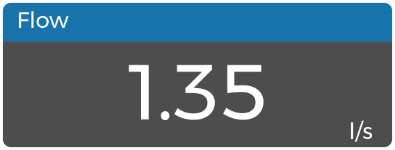
If there are no Modbus communication errors, and if no alarm condition is active (or defined), the header will be displayed in blue:
../_images/tile_blue.png

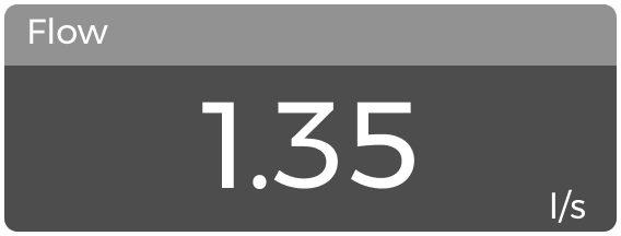
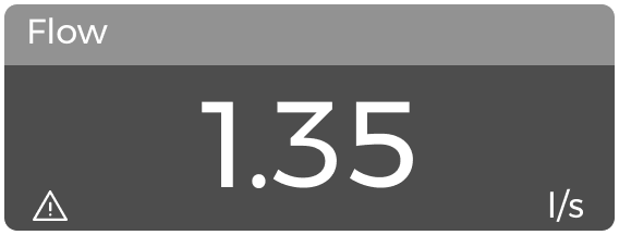
If the variable/register has a Modbus communication issue (where TP100 cannot access the register value), the header will be displayed in gray, as shown below:

../_images/tile_grey.png
If there is a Modbus communication error, the tile will not allow entering Preset mode (4. Preset Mode) to view the graph and/or modify the register value.
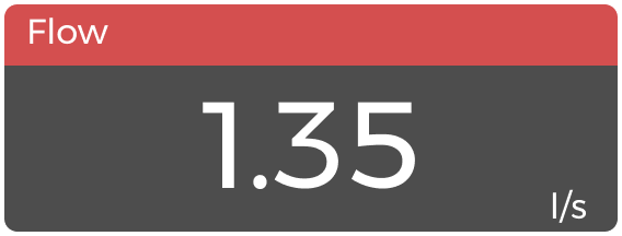
Finally, if an alarm condition has been defined during configuration, and the alarm condition is active, the header will be displayed in red:
../_images/tile_red.png

For more information on defining an alarm condition, refer to the Alarm and Alarm Threshold parameters described in the Configuration Wizard manual.

3.2. Tile Size

Tiles can be of two sizes: Half or Full.
Half tiles occupy exactly half of each row on the display (each page has 3 rows), while Full tiles occupy the entire row.
Therefore, each page can display 3 variables/registers on Full tiles (one per row) or six on Half tiles. Different types of tiles can be placed on the same page.
The tile size cannot be arbitrarily chosen, as it depends on the type of data to be displayed.
For example, a 32-bit variable will be displayed on a Full tile as it may have large values that cannot be properly displayed on a Half tile.
A 1-bit variable, however, will be displayed on a Half tile as the available space is sufficient to represent all possible values.
The tile size thus depends on the Variable Type configuration parameter, with more information available at this link: Configuration parameters.
For convenience, the variables associated with each type are listed below:
../_images/tile_size.png

1-2 HALF

  • 1bit - Boolean
  • 8bit - Byte
  • 16bit - Half signed
  • 16bit - Half unsigned

3 FULL

  • 32bit - Int signed
  • 32bit - Int unsigned
  • 32bit - Int signed inv
  • 32bit - Int unsigned inv
  • 32bit - Float
  • 32bit - Float inv

Note

The arrangement of the tiles on the display can be decided using the Configuration Wizard (Manual available here).


4. Preset Mode

If allowed by the type of register/variable, TP100 enables access to the Preset mode, where you can modify the read value and set it in the connected Modbus device.
To enter Preset mode, touch and hold a tile.
../_images/preset_page.png

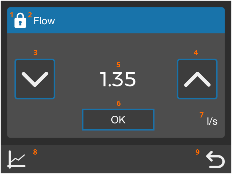
Below is a description of all the elements:

  • 1 This icon is displayed only if the register is password protected. In this case, before confirming a new value for the register, you will be asked to enter the password set during the configuration phase.
  • 2 Name assigned to the register during configuration.
  • 3 Decreases the register value. This icon will not be present if the register is defined as read-only.
  • 4 Increases the register value. This icon will not be present if the register is defined as read-only.
  • 5 Current register value. The value will continue to update even while remaining on this screen.
  • 6 Confirms the currently displayed value of the register after thr modification using the arrows. If the register is protected, the password entry screen will be displayed.
  • 7 Unit of measure.
  • 8 Touch this icon to view a real-time graph (4.2. Real-time Graph).
  • 9 This icon allows you to return to the Home screen.
Note that parameters such as name, unit of measure, access mode (read-only or read/write), and password can be defined during configuration. Refer to the Configuration Wizard user manual (Configuration Wizard).

4.1. Setting the Value of a Register

Once in Preset mode, if the register allows, it will be possible to modify and set a new value.
For this to happen, the following must be taken into account:
  • The Read Only option must not have been activated during configuration
  • A valid Modbus write command must have been associated with the register during configuration

In this case, arrows will appear next to the current register value, allowing you to increment (up) and decrement (down) the register value.

There are two ways to use the arrows:

  • Short touch
  • Long touch
In the first case, the rightmost digit, whether integer or decimal, will be incremented/decremented from the current value.
Holding an arrow for at least 3 seconds (long touch), the increment/decrement step will switch to the second digit from the right.
Continuing to hold the arrow for other 3 seconds it will step to one position further, modifying the third digit from the right, and so on.

Releasing the button and pressing it again with a short touch will apply the increment/decrement to the rightmost digit.

EXAMPLE

  • Starting value: 10.1
  • Applying a short touch on the up arrow will increment the decimal digit
  • Holding it for 3 seconds will start to increment the units
  • Holding it for 6 seconds will start to increment the tens

Once the desired value is selected, it will be possible to confirm the change by pressing the confirm button.

If the register is protected, the password entry screen will appear:

../_images/pin.png

In addition to the numeric keypad for entering the password, the following elements are present:

  • 1 Area where the numeric code will be entered. It will be highlighted in red if the entered code is incorrect.
  • 2 Touch this icon to view the entered code.
  • 3 Touch this icon to delete the last entered digit.
  • 4 Touch this icon to cancel the code entry and return to the Preset screen.
  • 5 This icon allows canceling the entry and returning directly to the Home screen.
  • 6 Appears only after entering at least 3 digits (minimum password length) and allows confirming the entered code.
Regardless of whether a numeric password entry is required, after confirming the value change TP100 will attempt to send the Modbus command to the connected device.
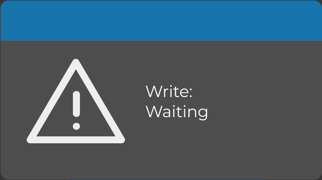
A pop-up with Write: Waiting will appear. If the operation is successful, the pop-up will disappear, and the Preset screen will be displayed again, showing the new value.
../_images/write_wait.png
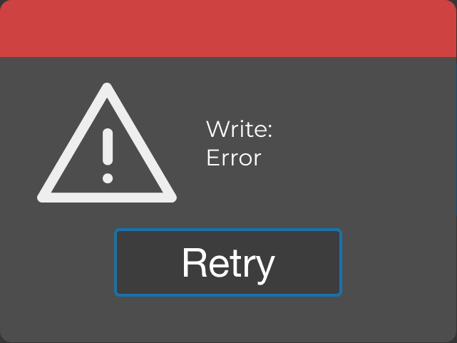
Otherwise, a pop-up with Write: Error will appear, and it will be possible to retry by pressing Retry.
../_images/write_error.png
If the issue persists, it is advisable to check the device configuration.

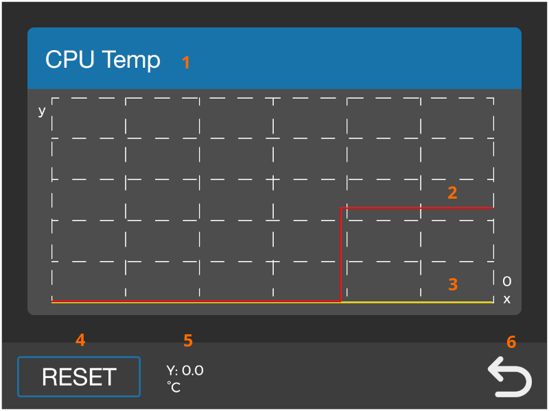
4.2. Real-time Graph

TP100 also allows viewing a real-time graph of the read values to verify the trend of the measured variable.

Once in Preset mode, simply select the graph icon. Below is a description of the elements that make up the screen:

../_images/graph_screen.png
  • 1 Name assigned to the register during configuration.
  • 2 The red trace represents the current value, starting from the right edge.
  • 3 The yellow trace represents zero. Useful especially for variables that oscillate between negative and positive values.
  • 4 The Reset button allows clearing the graph area and restarting the acquisition.
  • 5 This area displays the current value (and unit of measure) in figures.
  • 6 Touching the Back button returns to the Preset screen.

Below are the main features of the graph:

  • The graph starts generating when the screen is displayed. The displayed data is acquired in real time by TP100, and once the screen is closed, it will not be possible to view it again.
  • The graph generation starts from right to left, adding a point every second, up to a maximum of 100 points/seconds.
  • Autoscale is also present on the ordinate (y) axis, calculated based on the maximum value among the displayed points.
To view the register value in figures at a given moment, it is possible to touch any point in the graph area.
A vertical cursor (dashed blue line)will be added, attached to the trace representing the current value.
This cursor allows viewing the register value at that moment in the dedicated area (point 5).
The cursor will maintain its position on the x-axis even for subsequent points, updating the reported value in the dedicated area with each new received point.

Note

Due to limited space/resolution availability, some value variations may not be evident in the graph. For example, in the case of variables whose value extends in the order of tens/hundreds, variations related to the decimal part may not result in a visual change in the trend.
5. Communication Error Reporting

TP100 allows you to view any Modbus communication errors with the connected device to promptly identify potential issues.
Modbus communication errors can lead to 3 different notifications:
  • Register error
  • At least one register error
  • Communication error for all registers

5.1. Register Error

As previously mentioned, the header (top border) of the tile can change colors based on the register’s status.
If TP100 cannot access a register (possible causes: configuration errors, Modbus server device turned off, serial connection not connected), the header will turn gray.
There will also be an alarm icon at the bottom left (providing the same information as the gray header).
../_images/tile_grey_error.png

Note that in this case, it will not be possible to access the Preset mode. As soon as TP100 is able to acquire the register value again, the header will return to its natural color.

5.2. At Least One Register Error

If at least one register is in a communication error state, an icon will be displayed at the bottom left of the footer.

../_images/danger_footer.png
This notification allows you to promptly identify a communication error condition, even if it concerns a register not present on the currently displayed page.
The icon will disappear once all registers become accessible by TP100 again.

5.3. All Registers in Error

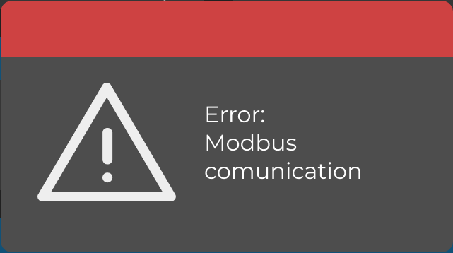
If TP100 encounters communication problems with all Modbus registers, the device will disable the Home screen (which would then be unusable).
This condition will also be highlighted by the following pop-up:
../_images/mb_error.png
The reasons leading to communication errors on all registers can be various.
Below is a list of the most common ones:
  • Serial connection not connected
  • TX/RX or A/B signals inverted
  • Wrong position selector on the serial
  • Incorrect baud rate (the baud rate of TP100 is 38400, not modifiable)
  • Modbus server device turned off
  • Incorrect Modbus address of the server device (to be modified in the device itself or in the TP100 configuration)
  • Incorrect definition of read commands in the TP100 configuration
If problems persist, check the configuration of the Modbus server device and TP100 (use the Configuration Wizard to minimize errors: Configuration Wizard).
As soon as communication with at least one register is restored, the pop-up will disappear, and it will be possible to use the Home screen again.

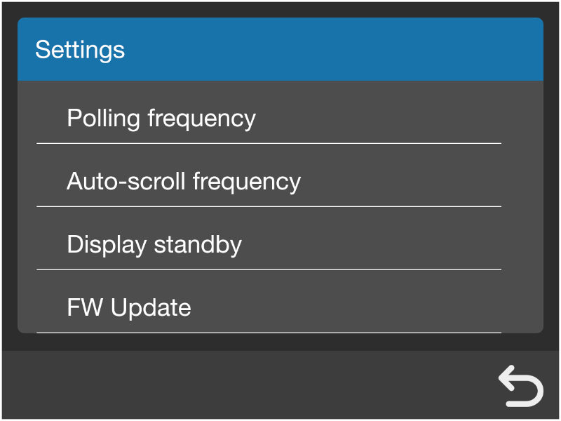
6. Settings Menu

At the bottom (footer) of the Home screen, there is the settings icon which allows access to the settings menu.

Once selected, a new screen will appear showing all available settings, navigable by scrolling the sidebar.

../_images/menu_settings.png

The available settings are as follows:

  • Polling frequency Allows you to change the reading frequency (in seconds) of the registers by TP100, specifying a value between 5 and 5000.
  • Auto-scroll frequency Allows enabling and deciding the automatic scrolling frequency of the Home screen pages. It is possible to set a period between 5 and 60, with steps of 5 seconds for each increment/decrement. Select 0 to disable the option.
  • Standby display Allows setting the inactivity time before putting the display on standby. Expressed in minutes, it is possible to set a value between 1 and 60. Select 0 to disable the option.¹
  • Update FW Allows starting the device FW update procedure. All details are available in the related chapter 10. Firmware Update.
  • Buzzer Allows activating (1) or deactivating (0) the internal buzzer feedback.

Parameters can be changed using the down2 and up2 arrows.

All changes take immediate effect once the confirm2 button is selected.

Finally, the Back button allows you to return to the Home screen.

Note

¹ The standby mode allows reducing power consumption. TP100 will continue to acquire the register values according to the set polling frequency.

Simply touch any point on the display to exit standby mode.


7. How to Configure TP100

TP100 can be configured in two ways:

All information regarding these methods can be found in their respective manuals (linked above).
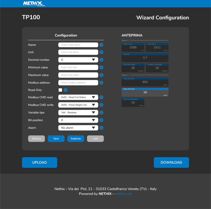
../_images/wizard.png
It is highly recommended to use the Configuration Wizard to minimize the chance of errors.
The online configurator generates the configuration file according to the JSON standard and prevents the entry of characters/parameters that could be misinterpreted by TP100.
Thanks to real-time preview, it also allows arranging tiles as desired and seeing the exact final display effect.
Additionally, it supports uploading previously created configuration files, which will be displayed in the preview and easily editable by the user.
Once a functional configuration file is created, it is advisable to save and make a backup copy before making changes.
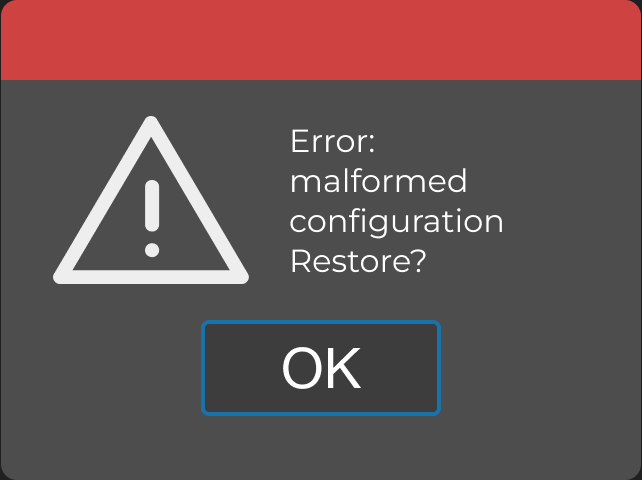
If a configuration file containing writing/formatting errors is uploaded to the device, TP100 will display an error message and ask if the user wants to restore the previous configuration.
The JSON configuration file currently loaded on the device can be found simply by connecting TP100 to your PC.

8. Uploading Configuration

Once a valid configuration file (in JSON format) has been generated, it can be uploaded to the internal memory of TP100.
To do this, simply connect the device (powered on) to your PC using a standard USB-C cable.
Below are the steps required to successfully complete the upload.
  1. Power on TP100 and wait for the Home screen to load.
  2. Connect the USB cable to the USB-C connector at the back of the device.
  3. Connect the other end of the cable to your PC.

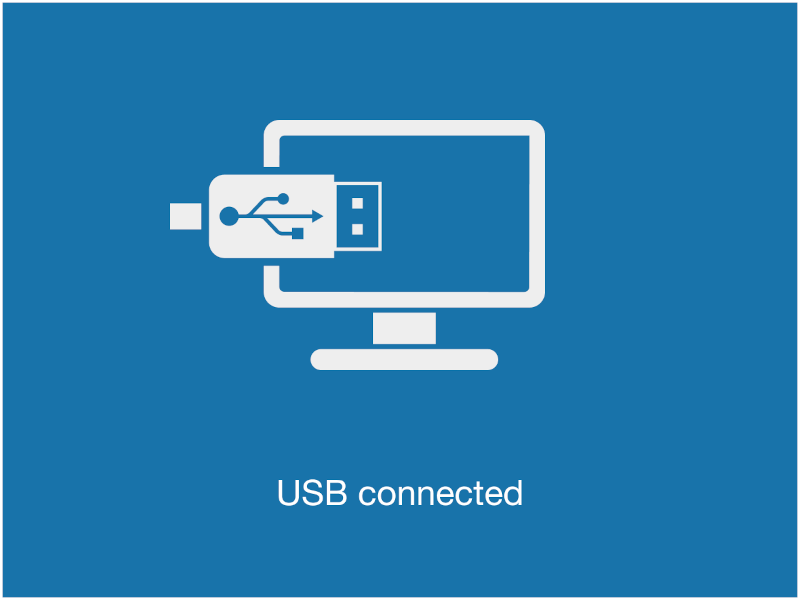
If the connection is successful, the following screen will be displayed:

../_images/usb_connected.png
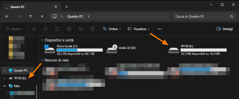
  1. At this point, the PC should recognize a new device named TP100. Identification will occur as if it were a USB data storage device.
  2. Using the PC’s file explorer, find the new TP100 device and open its path.
../_images/tp100_pc.png
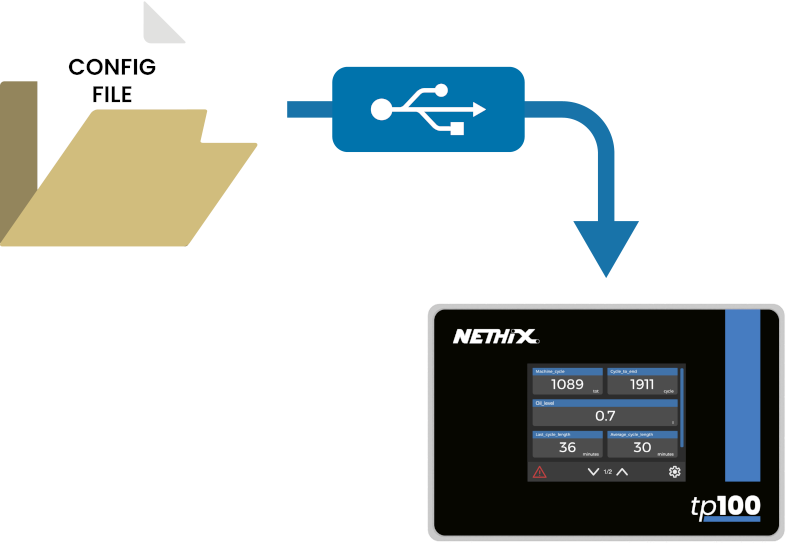
  1. Find the previously generated configuration file and copy it into the TP100 device via drag-and-drop (if supported by your PC) or simple copy-paste.
../_images/usb_copy.png
  1. Wait for the copy operation to complete; considering that the configuration file is very light, copying should not take more than a few seconds.
  2. Disconnect the USB-C cable from TP100.
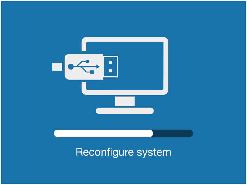
  3. The device will start reading the new configuration; during this process, the following screen will be displayed:
../_images/configuration_upload.png
  1. If the configuration is recognized as valid, the Home screen will immediately reflect the changes, and the device will be operational.
  2. Otherwise, TP100 will indicate an error and ask if you want to restore the previous configuration (which is still stored in its internal memory).
../_images/config_error.png

Note

Refer to the hardware manual (Hardware manual) for power and USB-C cable connections.

Note

The filename loaded into TP100 is not relevant. However, it is strictly necessary to keep the .json extension.

Warning

Some USB-C cables available on the market only carry power signals to the connector (this is the case, for example, with some cables used for smartphone battery charging).

To ensure that your PC correctly identifies TP100, make sure that the cable in use also carries data signals.

One way to verify this is by connecting your smartphone to the PC using a USB-C cable. If the smartphone is recognized, the cable can also be used for TP100.


9. Downloading Configuration

In addition to generating a new configuration file using Configuration Wizard, it is possible to obtain the currently loaded configuration file from the device (always in JSON format).
To do this, simply connect the device (powered on) to your PC using a standard USB-C cable.
Below are the steps required.
  1. Power on TP100 and wait for the Home screen to load.
  2. Connect the USB cable to the USB-C connector at the back of the device.
  3. Connect the other end of the cable to your PC.

If the connection is successful, the following screen will be displayed:

../_images/usb_connected.png
  1. At this point, the PC should recognize a new device named TP100. Recognition will occur as if it were a USB data storage device.
  2. Using the PC’s file explorer, locate the new TP100 device and open its path.
  3. Inside the newly opened folder, you will find a file named cfg.json.
  4. Copy and paste this file onto your PC.
The obtained file can be edited using a standard text editor (not recommended) or can be uploaded into the Configuration Wizard (recommended).
In the latter case, you can immediately preview the configuration (matching what is displayed on the screen) and easily modify the necessary parameters.

Note

Once downloaded to your PC, the file can be renamed as desired. However, it is essential to maintain the .json extension for future use.


10. Firmware Update

You can update the device firmware by requesting the update file from Nethix technical support.
Firmware updates may be necessary to resolve device functionality issues or to add new features.
Before proceeding with an update, ensure you have created a backup of the currently loaded configuration on the device.
Below are the steps required for a successful firmware update of TP100:
  1. Power on TP100 and wait for the Home screen to load.
  2. Touch the icon to access the settings menu (6. Settings Menu).
  3. Scroll until you find Update FW and select it.
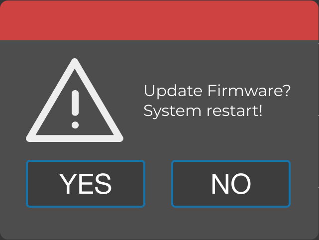
  4. Confirmation of intention to proceed will be requested, as shown in the following image:
../_images/confirm_update.png
  1. Confirm your choice by selecting YES. From this moment until the operations are complete, it is important not to turn off the device for any reason.
  2. The device will restart automatically. The following screen will be displayed:
../_images/bootloader.png
  1. Connect TP100 to your PC using a USB-C cable.
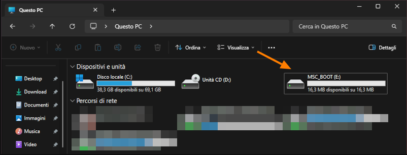
  2. The PC will recognize a new device named MSC_BOOT.
../_images/msc_pc.png
  1. Open the device path using your File Explorer.
  2. Inside the newly opened folder, you may find a file named README. It is not necessary to open the file, but its presence indicates that the device is correctly connected to the PC and in Update mode.
  3. Drag & drop (or copy-paste) the update file obtained from Nethix into the folder.¹
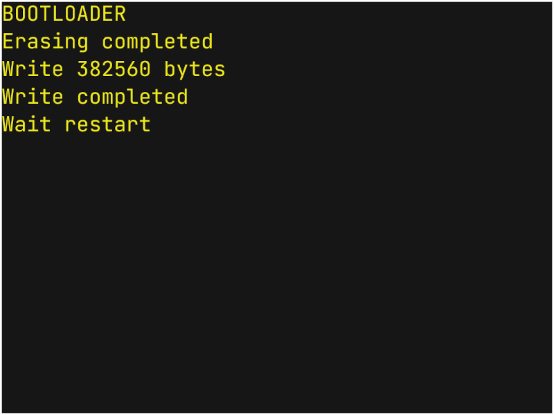
  4. Keep the USB-C cable connected. After the copy operation completes, the device will restart automatically and display the following screen²:
../_images/erasing_screen.png
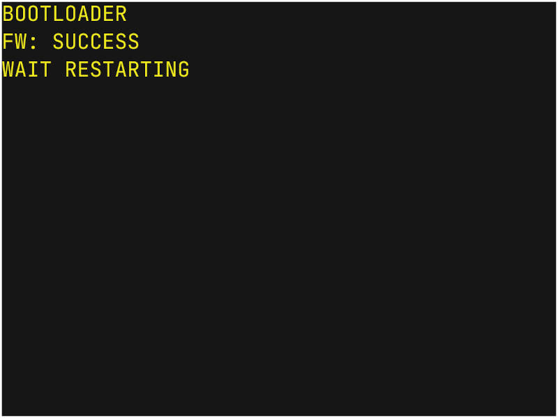
  1. At this point, the device will restart again (keep the USB-C cable connected). If the operations were successful, the following screen will be displayed:
../_images/update_success.png

Error

If FW: FAIL appears instead, it means the update was unsuccessful. Try turning off/on the device and repeat the operations. If the display remains completely black even after restarting the device, proceed to section 10.1. Device Reset.

  1. After a few seconds, TP100 will start normally, displaying the boot screen and then the Home screen. From the boot screen, you can verify if the firmware update was successful, as the new FW version will be displayed below the Nethix logo.
../_images/boot_screen.png
  1. At this point, you can safely disconnect the USB-C cable and resume using the device.

Note

¹ The update file must be named FWTP100.hex. Any other name will not be accepted, and the update procedure will fail.

Note

² The byte count shown in the image is purely indicative and may vary depending on the loaded FW version.

10.1. Device Reset

If issues are encountered during the update procedure (such as FW: FAIL appearing after uploading the update file), TP100 may become unusable.
In this case, the display may remain completely black even after a restart, without showing the boot screen.
There is a way to recover a TP100 device that ends up in this condition:
  1. Turn off the device and disconnect the USB-C cable.
  2. Locate the reset button on the board (refer to point 6 in this link 3. Connectors and Pinout).
  3. Press and hold the reset button while powering on the device.
  4. If successful, the following screen will appear:
../_images/bootloader.png
  1. You can release the reset button at this point.
  2. The FW needs to be reloaded, following the procedure described in chapter 10 from point 7 onwards (including).

If the device still does not start correctly, try repeating the procedure or contact Nethix support.