Genesys 3
1. Overview
Genesys is a Nethix Software that offers to the user a simple, intuitive and user-friendly interface for configuring the WE120. The WE120 manual can be found in the WE120.
It’s a lightweight software compatible with the following operating systems:
It allows to configure almost all aspects of the WE120:
- The basic parameters of the device
- The advanced parameters of the device
- Users
- I/O
- Alarms
- Expansion modules
In addition it allows to:
- Control inputs and outputs
- Upgrade the device
- Make a factory reset
Genesys communicates with WE120 through the RS232 Serial Port or through the USB mini-B port.
2. Installation
Note
The application program Genesys works properly only on a 64bit system.
2.1. Windows
- Download the USB driver for the Windows operating system, extract the files and run the file install.bat.
- Download the lastest version of the Genesys 3 for Windows.
- Double click on the downloaded executable file.
- Follow the installation wizard.
- Click on Next.
- Select the destination directory and click on Install.
- Once the installation is completed an icon will appear on the desktop.
- Connect the WE120 to the PC through USB or RS232.
- Turn-on the WE120.
- Start up the Genesys 3 by double clicking on the
 icon available on the desktop.
2.2. OS X
- Download the latest version of Genesys 3 for OS X systems
- Extract the files
- Connect the WE120 to the Mac through the USB port
- Turn-on the WE120
- Start up the Genesys 3
2.3. Linux
Download the latest version of Genesys 3 for Linux systems.
Install the prerequisites using the Linux distribution package manager:
Give permissions to the user for accessing the serial port of the PC. Modify through the preferred text editor the file /etc/group and add your user to the dialout group:
sudo vi /etc/group
dialout:x:20:utente
Logout and login
Connect the WE120 through the RS232 Port
Switch on the WE120
Run the Genesys 3
3. Communication initialization
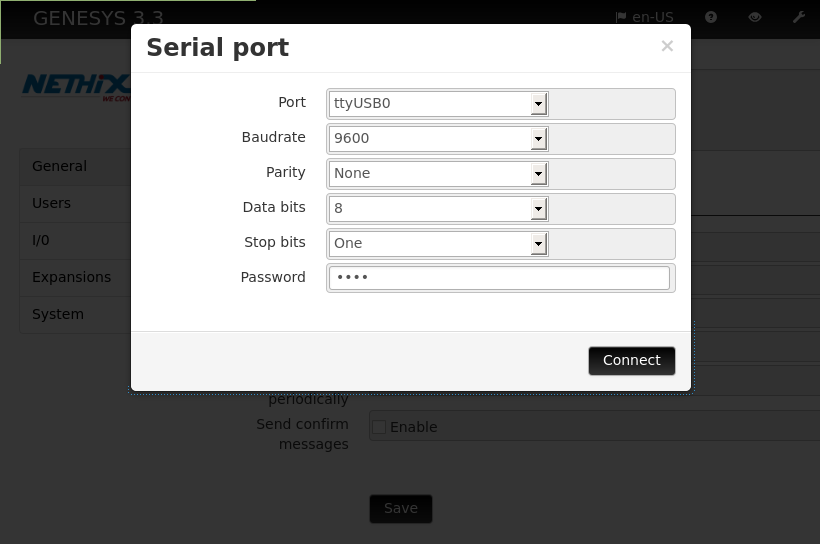
At the start up of Genesys the following window will be displayed:
The parameters of the port used for the communication between the WE120 and the PC must be entered.
The default parameters are:
- Porta: It may vary. For example, in windows the port could be COM0 whilst in Linux it could be ttyS0
- Baudrate: 9600
- Parity: None
- Data bits: 8
- Stop bit: Uno
- Password: 0000
Once entered the correct data, click on the tab Connect.
If the initialization is successful, the following message will appear:

Otherwise the following message will be displayed:

The communication is not successful if
- The WE120 is switched off
- The WE120 is not connected to the PC
- The wrong Port has been selected
- The Baudrate or some other serial communication parameters are not correct
Once the communication has been successfully initialized, it’s possible to start the configuration of the WE120.
4. User interface
Let’s start to familiarize with the web interface and its different sections and components.
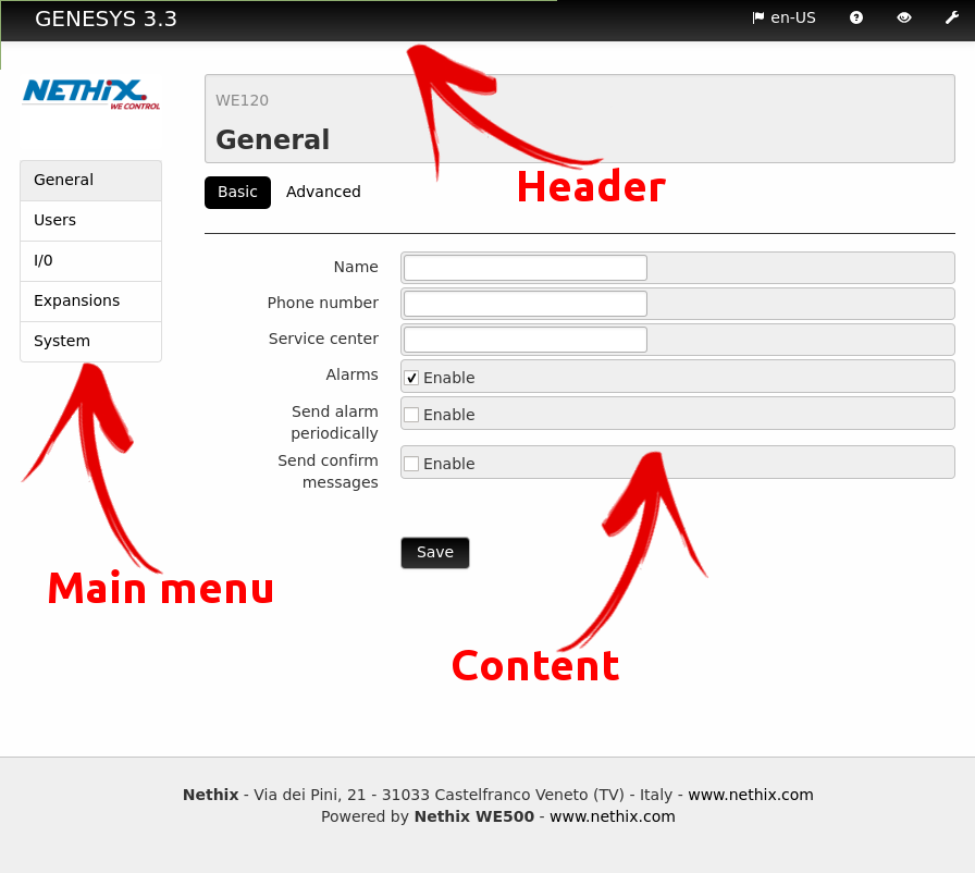
Each page of the interface is divided into three sections, as indicated below: header, main menu and content.
4.2. Main menu
The main menu area shows the Nethix Logo and all available options for browsing inside Genesys:
- General
- Users
- I/O
- Expansions
- System
4.3. Content
From this section the user can configure all the parameters of the WE120. This area changes dynamically according to the menu that the user wants to diplay.
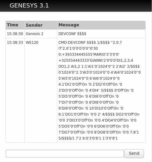
In this section the result of all executed commands will be displayed:
- green: the operation has been successfully completed
- red: the operation has not been successfully completed due to an error condition
5. General settings
In this section is possible to configure all general and basic parameters of the device, such as the name or the SIM number, or all the advanced parameters such as the activation of the only modem mode.
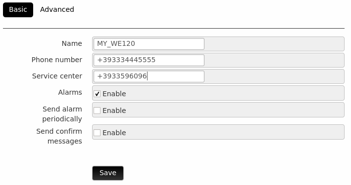
5.1. Basic settings
This area allows to set the general basic parameters of the WE120:
- Name: The name to be assigned to the device. Only alphanumeric characters [aA-zZ] and underscore _ are allowed.
- Telephone: The telephone number of the device, preceded by the plus sign + and the country code. For example, in Italy the telephone number starts with +39.
- Service Center: The SIM Provider Service Center
- Alarms: enables The sending of alarms to the user via SMS or Ring
- Sends alarms periodically: Enables the sending of a periodical message in case of alarm
- Sends confirmation message: Enables the sending of a confirmation message for each executed command
After completing all the fields, it’s necessary to press Save in order to save the settings.
5.2. Advanced settings
In this section is possible to set the general advanced parameters of the WE120.
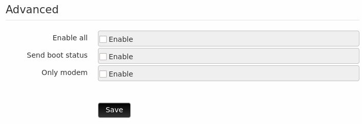
5.2.1. Advanced
It is possible to set the following options:
- Enable all: Any telephone number (even if they are not registered in the device) can send/receive messages to/from the WE120.
- Send boot status: Send an SMS at every start up of the device.
- Only modem: Enables the only modem mode.
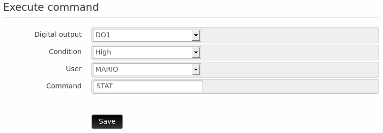
5.2.2. Execute command
From this area it is possible to allow the WE120 to execute a command when a digital input reaches a defined value.
The result of the command will then be sent to the specified user.
- Digital output: The digital output associated to the command
- Condition: The required status of the output to execute the command
- User: The telephone number or name of a registered user
- Command: The command to be executed
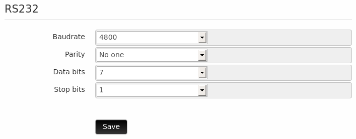
5.2.3. RS232
In this section the parameters of the RS232 serial port are configured:
- Baudrate
- Parity
- Data bit
- Stop bit
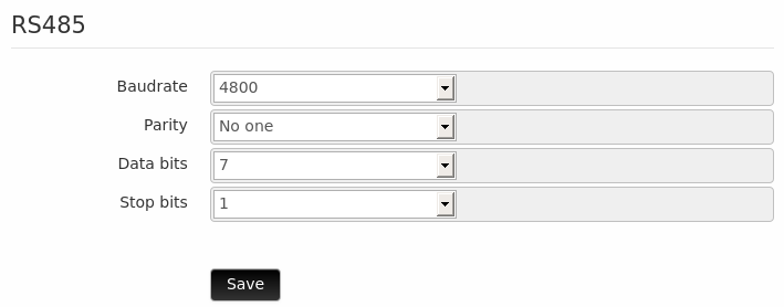
5.2.4. RS485
In this section the parameters of the RS485 serial port are configured:
- Baudrate
- Parity
- Data bit
- Stop bit
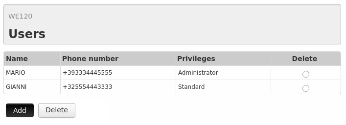
6. Users
This page shows the list of all users registered in the device.
A table complete with name, telephone number and users privileges is given.
It’s possible to delete a user just by selecting it on the column Delete of the table and then clicking on the Delete button.
To add a new user it’s sufficient to click on the Add button; for editing just click on the user to be modified.
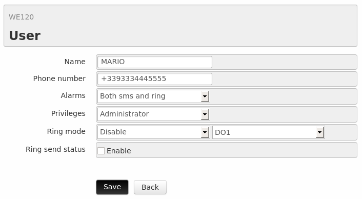
The page for adding or editing a User is the following:
It allows to set the following parameters:
- Name: The user name.
- Telephone: User telephone number preceded by the plus sign + and the country code. For example, in Italy the telephone number starts with +39.
- Alarms: Select the type of alarm to be sent to the user:
- No alarm
- Only SMS alarms
- Only ring alarms
- Both SMS and Rings
- Privileges: The user’s privileges:
- Read only: The user can only read the I/O status.
- Administrator: The user can both read and configure the I/O; it can also configure the WE120.
- Standard: The user can read and configure only the inputs and outputs selected on the field variables.
- Ring Mode: Turn- on/off or switch the status of an output through a Ring
- Send status through Ring: It enables the sending of the I/O status through a Ring.
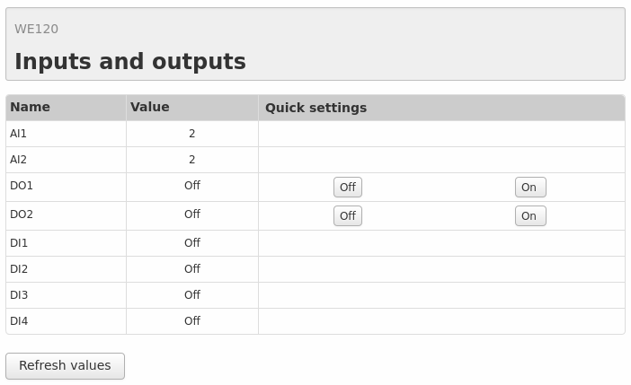
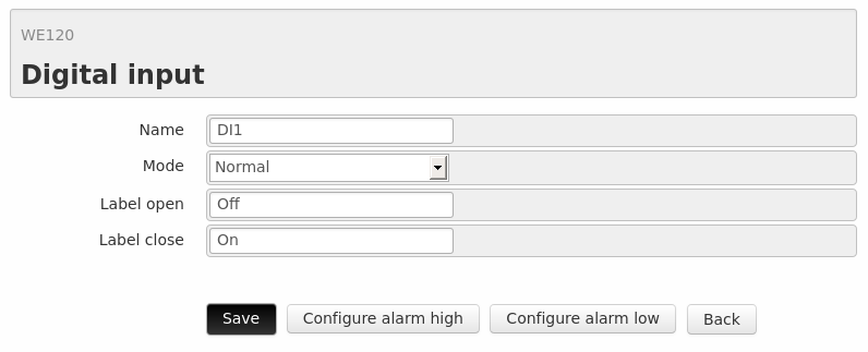
7. I/O
This section shows the list of all the available inputs and outputs of the WE120.
In the table is given the name and the value and, in case of the digital outputs, also a tab for activating or deactivating the output.
On the lower part of the table there is an Update values button that allows to update the I/O status.
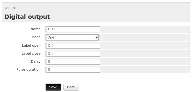
7.2 Digital outputs
For entering the configuration page of a digital output, click on the relevant line of the table.
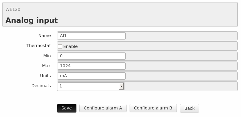
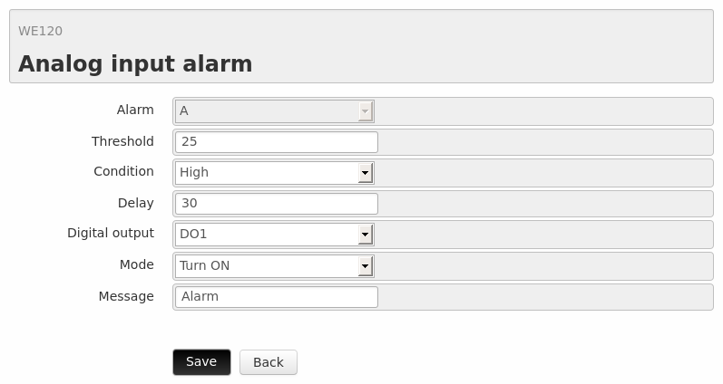
From this page it is possible to configure following parameters:
- Name: The digital output name.
- Mode: Activation mode of the output:
- Open: Opens the relay
- Closed: Closes the relay
- Pulse open: Opens the relay for X seconds
- Pulse close: Closes the relay for X seconds
- Label open: The string to be displayed when the relay is open
- Label closed: The string to be displayed when the relay is closed
- Delay: The number of seconds between the command and the activation of the relay
- Pulse duration: Duration of the pulse, expressed in seconds
By clicking on the Save button the modifications of the parameters will be applied.
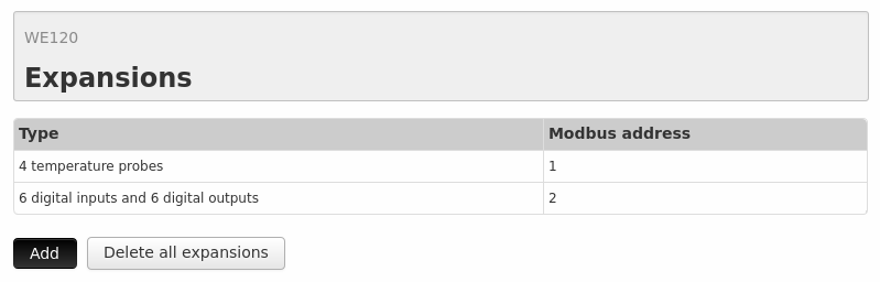
8. Expansions
This pages shows a table with the connected expansions and their respective Modbus addresses.
It is possible to add new expansions by clicking in the Add button, whilst all the expansion can be removed at once by clicking in the Delete all expansions button.
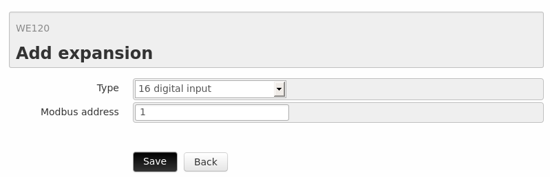
8.1. Adding expansions
To add a new expansion the following parameters must be set:
- Type: The type of expansion:
- 16 digital input
- 6 digital input and 6 digital output
- 4 analog inputs
- 4 analog inputs black
- 4 temperature probes
- Modbus address: The expansion’s Modbus address
Once an expansion has been added, the 7. I/O page will display the new inputs and/or outputs that corresponds to this expansion.
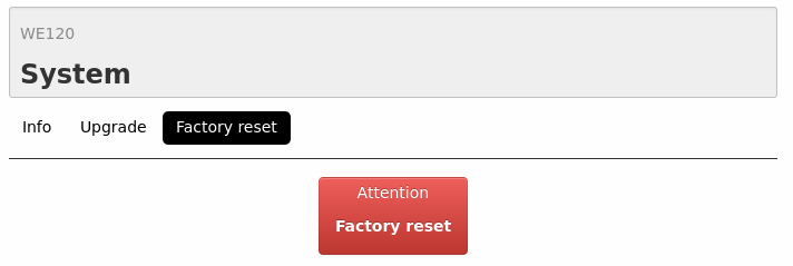
9. System
This chapter is dedicated in three areas:
- Info
- Upgrade
- Factory reset
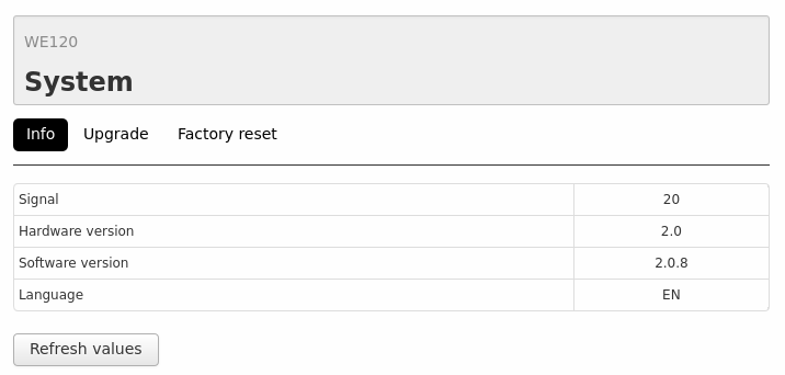
9.1. Info
In this area is displayed the following information that regards the device:
- Signal: The GSM signal level. The signal number can be interpreted as follows:
- 1 to 7: GSM signal is too low for a correct operation of the device
- 8 to 12: GSM signal is low
- 13 to 18: GSM signal is good
- Higher than 18: GSM signal is very good
- Hardware version
- Software version
- Language: The software language currently installed in the WE120. The SMS messages that are sent/received by the WE120 depend on this setting. For example, if the EN language is set, the WE120 will expect message commands written in English.
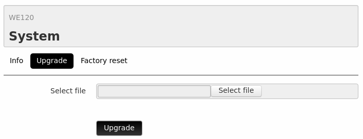
9.2. Update
In this area the WE120 firmware can be updated.
This is a quick and simple procedure:
- Download the latest firmware file firmware
- Select the just downloaded file in the Select file field
- Click on the Upgrade button.
- Turn-off the WE120
- Turn-on the WE120
- Wait for the update procedure to finish. It typically takes ~3 minutes.
For details, please read the firmware update guide.
9.3. Factory reset
Using this button it is possible to clean all the device configuration. All the previous configuration will be lost except the serial port parameters. If a firmware upgrade was executed before the factory reset, that firmware will remain.