1. Overview
The WE500 can manage several master and/or slave modbus networks at the same time.
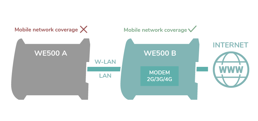
The present guide shows, through a simple example, how to manage a modbus network with two WE500.
Assume that in the installation site of the WE500 A there is no 3G coverage, whilst in the installation site of the WE500 B there is a good 3G coverage. The communication between both WE500 is established through a Wi-Fi network. The user wants to monitor and control the WE500 A site by taking advantage of the 3G connectivity of the WE500 B.
A master modbus network with its commands and variables will be set for the WE500 B, whilst a slave modbus network also with its commands and variables will be set for the WE500 A.
Note
This guide is useful for quickly learning a specific functionality of the WE500.
Notice that this document does not cover all the functionalities of the WE500. Please refer to the software and hardware manuals for in-depth explanations and a deeper understanding of the WE500.
2. WE500 A Slave configuration
Setting up the WE500 A and the TCP/IP modbus network.
2.1 General configuration
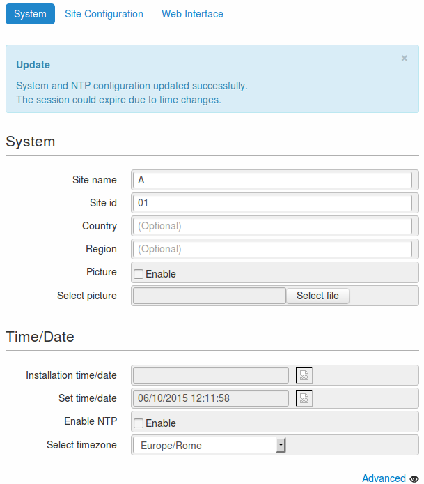
Assign a name and an id to identify the WE500 A:
- Go to the page Administration –> General Setup –> System.
- Fill in the fields as specified below.
- Save the configuration through the Save button, at the bottom of the page.
2.2 Modbus variables configuration
Setting up the variables of device A:
- Go to the page Administration -> Variables.
- Click on the New button, to create a new variable.
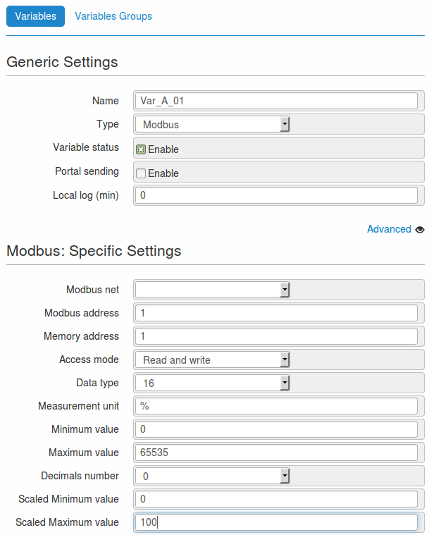
- On the new page, fill in the fields as indicated below.
- Name: Var_A_01
- Type: Modbus
- Modbus net: do not associatewith any networks
- Modbus address: 1
- Memory address: 1
- Access mode: Read and write
- Data type: 16
- Measurement unit: %
- Minimum value: 0
- Maximum value: 65535
- Decimals number: 0
- Scaled Minimum value: 0
- Scaled Maximum value: 100
- Leave the other fields with default values.
- Save the configuration through the Save button, at the bottom of the page.
- Use the Create new variable button, available at the bottom of the same page, to create a new variable.
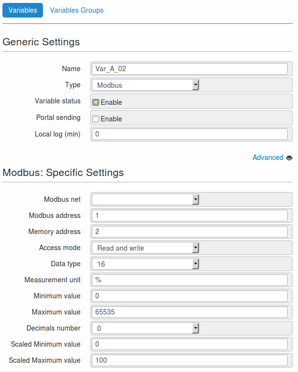
- Fill in the fields as indicated below.
- Name: Var_A_02
- Type: Modbus
- Modbus net: do not associate with any networks
- Modbus address: 1
- Memory address: 2
- Access mode: Read and write
- Data type: 16
- Measurement unit: %
- Minimum value: 0
- Maximum value: 65535
- Decimals number: 0
- Scaled Minimum value: 0
- Scaled Maximum value: 100
- Leave the other fields with default values.
- Save the configuration through the Save button, at the bottom of the page.
Note
The values entered in the above screen are used only for illustrative purposes.
By using 16 bit it is possible to obtain 65535 as maximum value in decimal base.
In order to have properly working variables, it is necessary to configure them according to the devices connected to the WE500.
2.3 Modbus commands configuration
Setting up the commands to read and write the values of the variables.
2.3.1 Commands of Var_A_01 variable
- Go to the page Administration –> Modbus –> Commands.
- With the Add new commands button, create a new command.
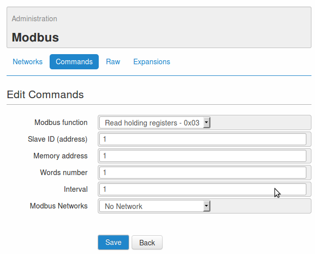
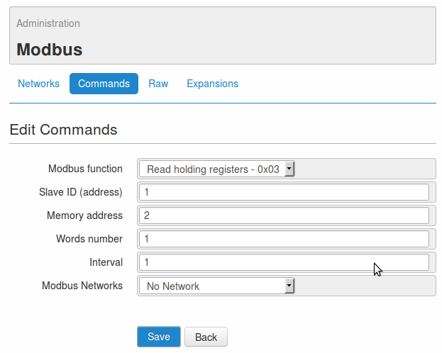
- On the new page, fill in the fields as indicated below.
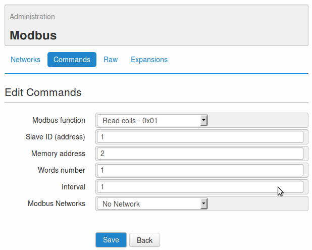
- Modbus function: Read holding registers - 0x03
- Slave ID (address): 1
- Memory address: 1
- Words number: 1
- Interval: 1
- Modbus network: do not associate with any networks
- Save the configuration through the Save button, at the bottom of the page.
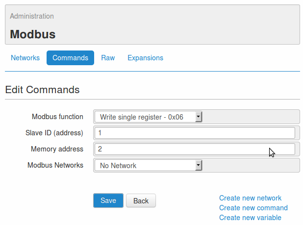
- Use the Create new commands button at the bottom right of the same page, to create a new command.
- Fill in the fields as indicated below.
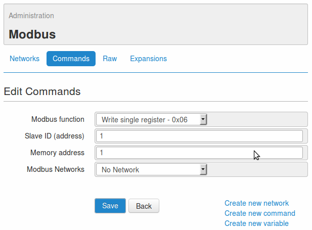
- Modbus function: Write single register - 0x06
- Slave ID (address): 1
- Memory address: 1
- Modbus network: do not associate with any networks
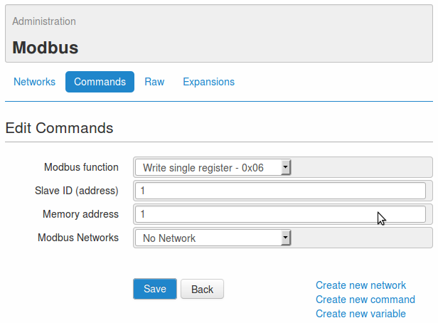
- Save the configuration through the Save button, at the bottom of the page.
Note
The values entered in the above screen are used only for illustrative purposes.
In order to have properly working variables, it is necessary to configure them according to the devices connected to the WE500.
2.3.2 Commands of Var_A_02 variable
- Go to the page Administration –> Modbus –> Commands.
- With the Add new commands button create a new command.
- On the new page, fill in the fields as indicated below.
- Modbus function: Read holding registers - 0x03
- Slave ID (address): 1
- Memory address: 2
- Words number: 1
- Interval: 1
- Modbus network*: do not associate with any networks
- Save the configuration through the Save button at the bottom of the page.
- Use the Create new commands button at the bottom right of the same page, to create a new command.
- Fill in the fields as indicated below.
- Modbus function: Write single register - 0x06
- Slave ID (address): 1
- Memory address: 2
- Modbus network: do not associate with any networks
- Save the configuration through the Save button, at the bottom of the page.
Note
The values entered in the above screen are used only for illustrative purposes.
In order to have properly working variables, it is necessary to configure them according to the devices connected to the WE500.
2.4 TCP modbus network Slave configuration
Setting up the modbus Slave network using the TCP protocol:
- Go to the page Administration -> Modbus -> Networks.
- Create a new network with the Add new network button.
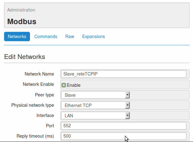
- On the new page, fill in the fields as indicated below.
- Network name: Slave_reteTCPIP
- Network enable: enabled
- Peer type: Slave
- Physical network type: Ethernet TCP
- Interface: LAN
- Port: 552
- Reply timeout (ms): 500
- In the section commands, select the commands 0x03(slave:1-addr:1), 0x03(slave:1-addr:2), 0x06(slave:1-addr:1) and 0x06(slave:1-addr:2), then link them to the network by pressing the > button.
- In the section variable, select the variables Var_A_01 and Var_A_02, then link them to the network by pressing the > button.
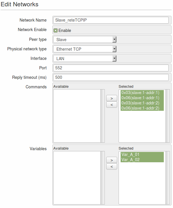
- Save the network set up using the Save button.
Note
The values entered in the above screen are used only for illustrative purposes.
In order to have properly working variables, it is necessary to configure them according to the devices connected to the WE500.
3. WE500 B Master configuration
Setting up the WE500 B and the TCP modbus network.
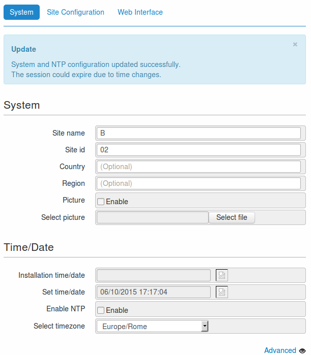
3.1 General configuration
Assign a name and an id to identify the WE500 B.
- Go to the page Administration –> General Setup –> System.
- Fill in the fields as specified below.
- Save the configuration through the Save button, at the bottom of the page.
3.2 Configurazione variabili modbus
Setting up the variables of device B:
Notice that these variables will have the same configuration as the variables of device A.
- Go to the page Administration -> Variables.
- Click on the New button, to create a new variable.
- On the new page, fill in the fields as indicated below.
- Name: Var_B_01
- Type: Modbus
- Modbus net: do not associate with any networks
- Modbus address: 1
- Memory address: 1
- Access mode: Read and write
- Data type: 16
- Measurement unit: %
- Minimum value: 0
- Maximum value: 65535
- Decimals number: 0
- Scaled Minimum value: 0
- Scaled Maximum value: 100
- Leave the other fields with default values.
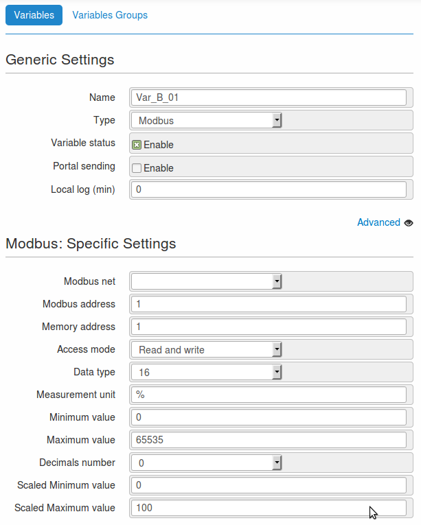
- Save the configuration through the Save button, at the bottom of the page.
- Use the Create new variable button, available at the bottom of the same page, to create a new variable.
- Fill in the fields as indicated below.
- Name: Var_B_02
- Type: Modbus
- Modbus net: do not associate with any networks
- Modbus address: 1
- Memory address: 2
- Access mode: Read and write
- Data type: 16
- Measurement unit: %
- Minimum value: 0
- Maximum value: 65535
- Decimals number: 0
- Scaled Minimum value: 0
- Scaled Maximum value: 100
- Leave the other fields with default values.
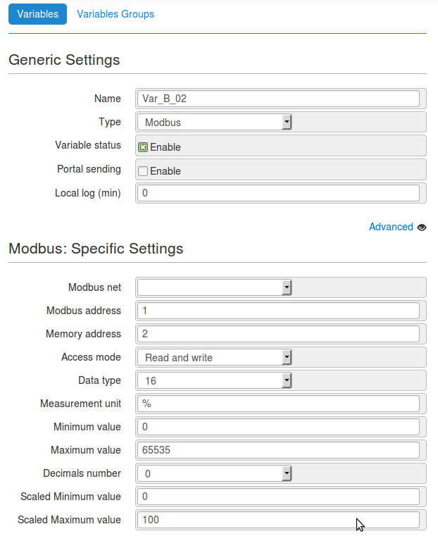
- Save the configuration through the Save button, at the bottom of the page.
Note
The values entered in the above screen are used only for illustrative purposes.
By using 16 bit it is possible to obtain 65535 as maximum value in decimal base.
In order to have properly working variables, it is necessary to configure them according to the devices connected to the WE500.
3.3 Modbus commands configuration
Setting up the commands to read and write the values of the variables.
3.3.1 Commands of the variable Var_B_01
- Go to the page Administration –> Modbus –> Commands.
- With the Add new commands button, create a new command.
- On the new page, fill in the fields as indicated below.
- Modbus function: Read holding registers - 0x03
- Slave ID (address): 1
- Memory address: 1
- Words number: 1
- Interval: 1
- Modbus network*: do not associate with any networks
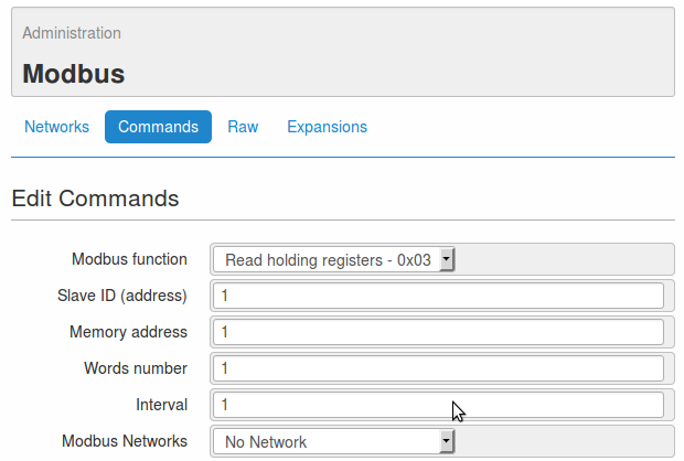
- Save the configuration through the button Save.
- Use the Create new commands button at the bottom right of the same page, to create a new command.
- Fill in the fields as indicated below.
- Modbus function: Write single register - 0x06
- Slave ID (address): 1
- Memory address: 1
- Modbus network: do not associate with any networks
- Save the configuration through the button Save.
Note
The values entered in the above screen are used only for illustrative purposes.
In order to have properly working variables, it is necessary to configure them according to the devices connected to the WE500.
3.3.2 Commands of the variable Var_B_02
- Go to the page Administration –> Modbus –> Commands.
- With the Add new commands button create a new command.
- On the new page, fill in the fields as indicated below.
- Modbus function: Read holding registers - 0x03
- Slave ID (address): 1
- Memory address: 2
- Words number: 1
- Interval: 1
- Modbus network: do not associate with any networks
- Save the configuration through the button Save.
- Use the Create new commands button at the bottom right of the same page, to create a new command.
- Fill in the fields as indicated below.
- Modbus function: Write single register - 0x06
- Slave ID (address): 1
- Memory address: 2
- Modbus network: do not associate with any networks

- Save the configuration through the button Save.
Note
The values entered in the above screen are used only for illustrative purposes.
In order to have properly working variables, it is necessary to configure them according to the devices connected to the WE500.
3.4 TCP modbus network Master configuration
Setting up the modbus Master network with the TCP protocol:
- Go to the page Administration -> Modbus -> Networks.
- Create a new network with the Add new network button.
- On the new page, fill in the fields as indicated below.
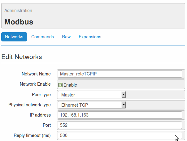
- Network name: Master_reteTCPIP
- Network enable: enabled
- Peer type: Master
- Physical network type: Ethernet TCP
- IP address: 192.168.1.163
- Port: 552
- Reply timeout (ms): 500
- In the section commands, select the commands 0x03(slave:1-addr:1), 0x03(slave:1-addr:2), 0x06(slave:1-addr:1) and 0x06(slave:1-addr:2), then link them to the network by pressing the > button.
- In the section variable, select the variables Var_B_01 and Var_B_02, then through the > button link them to the network.
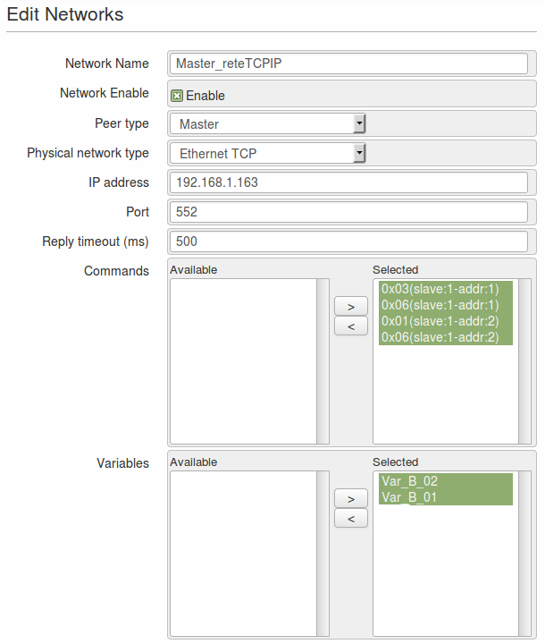
- Save the network set up using the Save button.
Note
The values entered in the above screen are used only for illustrative purposes.
In order to have properly working variables, it is necessary to configure them according to the ethernet network where the WE500 is going to be connected.
In order to establish a communcation channel between two WE500, they must be connected to the same network, i.e.they must have the same IP-address prefix (for example: 192.168.1).
The configurations of the WE500s are now completed and the devices are ready to operate as described at the beginning of the present document.
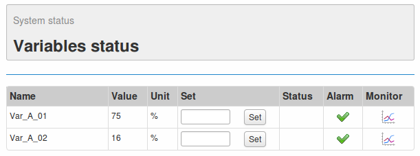
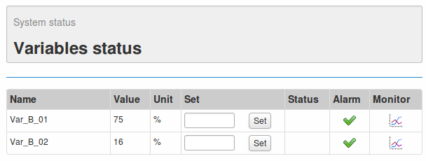
On the page Status -> Variables status it’s also possible to display the values of the variables, collected from the devices connected to the WE500s.