Software Manual

../_images/we200.png

1. General information

1.1. About this document

Present manual describes in details all functionalities of WE200, implemented in the Software version 3.2.4, released on October 2018.
Please make sure that the Software Version of your WE200 is updated to the latest release mentioned on this manual, in order to avoid discrepancies between the versions.
The software version could be find on the “Info” page, through the path Administration –> System –> Info.
The software version is indicated in the second upper right frame, always available in the WE200’s web interface.

In case of questions and issues not covered by present manual, you can contact Nethix Customer Support for further information:

Email: support@nethix.com

Phone: +39 0423 770750

Web Site: nethix.com

1.2. Overview

WE200 is a secure feature-rich 3G/LTE industrial gateway solution that allows to remotely access any device or machine through the serial, USB or Ethernet interfaces such as a PLC or HMI for configuration or maintenance purposes.

WE200 provides a secure VPN connection between the device or machine and the workstation where the SCADA or HMI software is running. A single WE200 can be used to manage more the one device or machine simultaneously and it is highly compatible with any device or machine that uses an RS232, RS485, USB or TCP/IP serial port, independently of the used protocol.

The built-in Web interface allows to easily configure and update the device by using only a standard browser.

In the following sections all these concepts and their use through the WE200 will be described.


2. Remote Access and Remote Maintenance

Using the industrial gateway function of the WE200, it’s possible to establish a secure connection to one or more remote devices or industrial machines ( PLC, SCADA, HMI operator panel and so on..), basing on the VPN network.

Once properly configured, the WE200 allows the user to access the USB and Ethernet serial ports of the monitored industrial device, in order to permit the programming, the monitoring and the remote assistance.

2.1 Configuration

For the remote access operations it’s possible to use all available serial ports of the WE200 (No.2 RS232 and No.1 RS485), the USB port and the 4 RJ45 Ethernet interfaces.

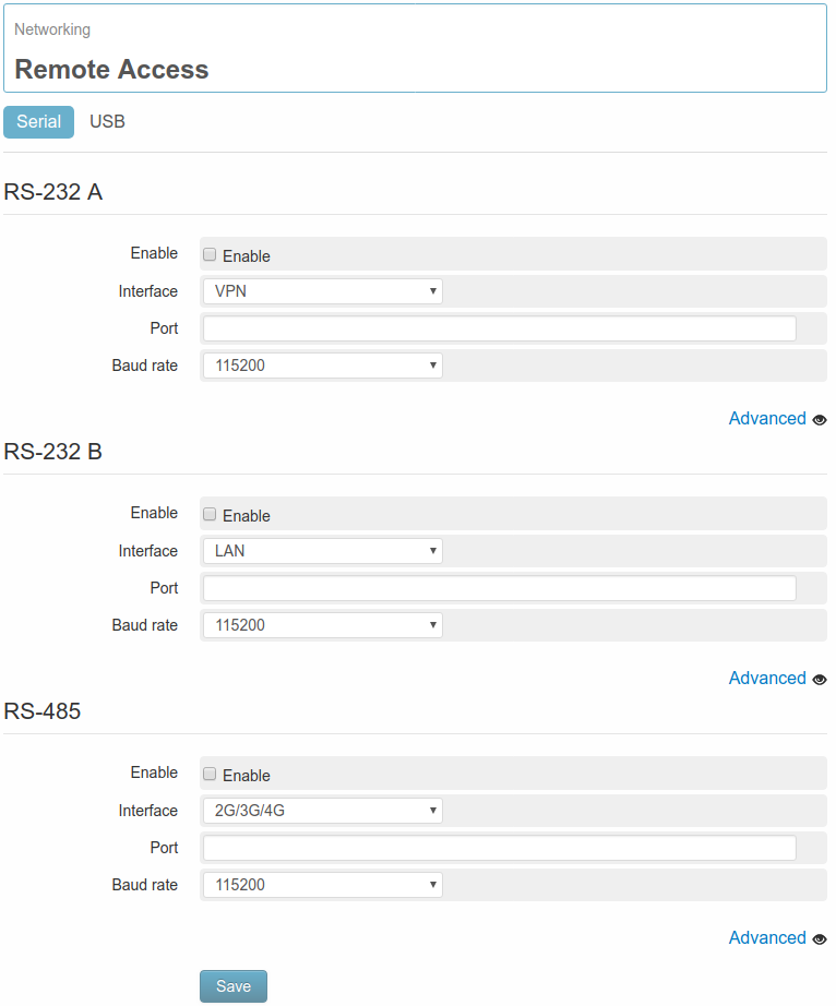
To enable the remote access function on serial port it’s necessary to enter the menu page Networking → Remote Access-→ Serial.

../_images/networking_remote_access_serial1.png

From this page it’s possible to activate the service on one or more serial interfaces, among those available on the WE200. First of all it must be activated the Enable option of the required serial port, then the following additional parameters shall be added:

  • Interface It allows to select the network interface to be used for reaching the WE200 remotely
  • Port It allows to define the virtual port for the WE200 to be associated with selected interface
  • Baud rate It allows to set the communication speed of the serial port

Clicking on Advanced the following advanced parameters are available:

  • Data bit Number of data bit on each character (default: 8)
  • Parity Bit of Parity (default none)
  • Stop bit Number of bit for stop (default 1)
  • Line editing buffer Enable/disable the option (disabled by default)
  • Hardware flow control Enables/disables the option of the flow control on sent/received files (disabled by default)

If not specifically required by the producer of the device to be interfaced with the WE200, it’s highly recommended not to change the parameters under the section Advanced.

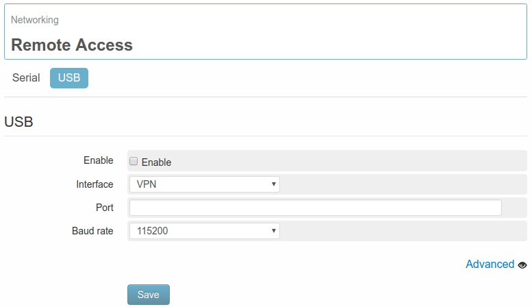
From the page Networking → Remote access → USB it’s possible to enter the section dedicated to the configuration of the USB Interface:

../_images/networking_remote_access_usb.png

The parameters that can be configured here, are the same as for the serial interfaces:

  • Interface It allows to select the network interface to be used for reaching the WE200 remotely
  • Port It allows to define the virtual port of the WE200 to be associated with selected interface
  • Baud rate It allows to set the communication speed of the serial port

Clicking on Advanced the following advanced parameters are available:

  • Data bit Number of data bit on each character (default: 8)
  • Parity Bit of Parity ( default none)
  • Stop bit Number of bit for stop (default 1)
  • Line editing buffer Enables/disables the option (disabled by default)
  • Hardware flow control Enables/disables the option of the flow control on sent/received files (disabled by default)

If not specifically required by the producer of the device to be interfaced with the WE200, it’s highly recommended not to change the parameters under the section Advanced.

2.2 Functioning

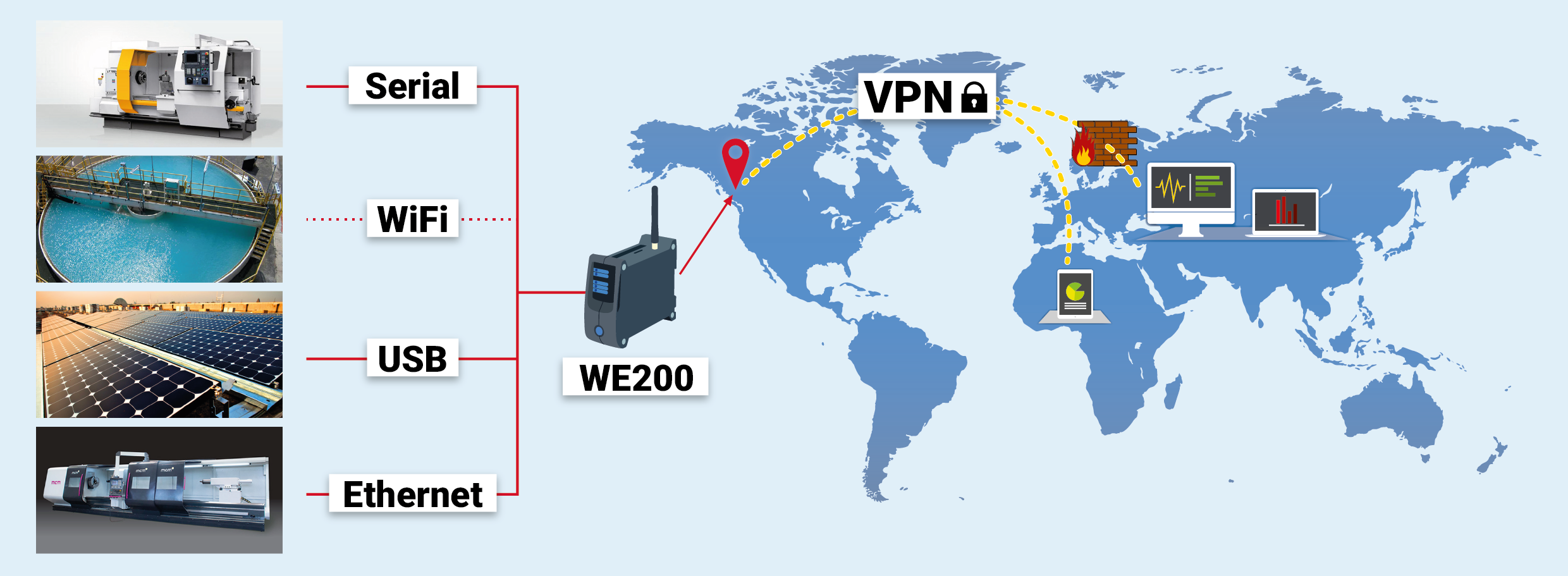
The Remote Access function allows to communicate remotely with any device/machinery connected to one of the serial interfaces or USB available on WE200, regardless of the used communication protocol.

../_images/networking_remote_access_img1.png

The Remote Access function, combined with the VPN service, allows to bypass potential firewalls and grants a high level of security.

../_images/networking_remote_access_img2.png

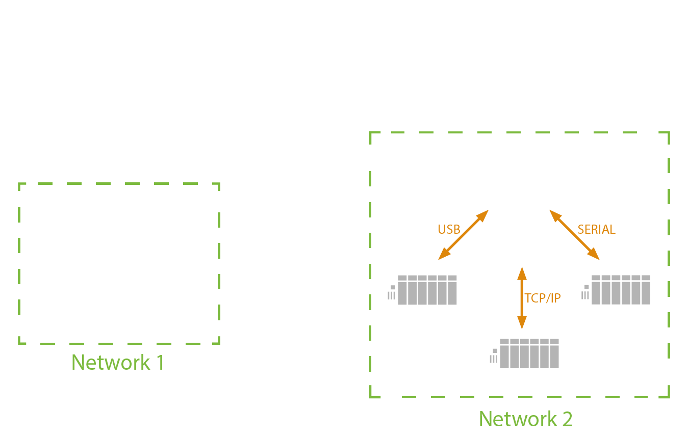
Thanks to the free software Quick Tunnel (QuickTunnel) it’s also possible to integrate the Remote Access function to the user PC: when launched, this software creates some virtual serial ports on the PC, that will be automatically connected to those configured on the WE200.

../_images/networking_remote_access_img3.png

A typical application is for example when a device/industrial machine needs to be connected through serial port, USB or Ethernet, to a PC, where a proprietary software is installed. In this case the WE200 works as a “bridge” to connect the PC with the machinery:

  • The serial port ( USB or Ethernet) of the device to be controlled, is connected to the one available on the WE200
  • Through the Remote Access function the WE200 makes remotely available the serial port of the device, to be monitored
  • Through the Quick Tunnel service, it will be created a virtual serial port, connected to the one available on the WE200
  • The control software of the device will communicate with the created virtual serial port.

3. Connectivity

Beside the main functions described on the preceding chapters, the WE200 allows to configure parameters related to connectivity, in order to meet all customers requirements.

All settings of the network interface, the services and the functions regarding the connectivity of the device are available under the menu section Networking.

3.1. Network interfaces

From the page Networking → Interfaces it’s possible to access the sections that allow to configure and start-up the different network interfaces and the different services.

  • Modem
  • LAN
  • WLAN (if available)

all network interfaces can be activated concurrently.

3.1.1. Data connection and SMS

WE200 allows to establish a HSPA/LTE connection (according to the modem required at order confirmation) in order to enter the web interface of the device and send data or emails, even if no Ethernet or Wi-Fi connections are available.

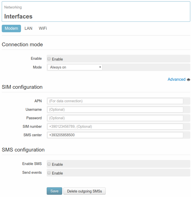
In order to activate the connection enter the page Networking → Interfaces → Modem.

../_images/interfaces_modem2.png

DATA CONNECTION

Once enabled the service with a flag on the field Enable, it’s required to specify whether the connection must be always on or on demand.

  • Always on: The WE200 will keep the connection always on. In case it should be interrupted (missing credit, Signal not available..) the connection will be restored as soon as possible.
  • On demand: the connection is activated on request by an authorized user through a Wakeup message (7. Commands) and after 15 minutes is automatically disabled. If the activated services require a connection for data sending or email sending.., the connection of the WE200 will automatically be closed at the end of the configured operations.

If the parameters have been properly configured, after a few minutes the HSPA/LTE connection will be activated. On the status panel, positioned on the right side of the web interface, the HSPA/LTE indicator will become green and beneath it the connection uptime and the relevant IP address will be displayed.

There are some advanced parameters, that can be entered clicking on the option Advanced:

../_images/interfaces_modem_adv2.png
  • Keepalive server 1 WE200 checks the connectivity status, trying to reach some preset server at regular intervals. This allows the system to detect any possible critical issue and react promptly to restore the connectivity. If required by the user, the servers used for the keepalive function can be modified
  • Keepalive server 2 Allows to configure a second server for the keepalive function, to be used in case the first one cannot be reached
  • Address/Control compression It enables/disables the compression of the address/control fields during the negotiation. With exception of particular situations, it’s normally recommended not to change the default settings (enabled)

Make sure that the HSPA/LTE connection has been successfully established, by checking if all necessary operations have been executed:

  • Provide the WE200 with an enabled data SIM card (rechargeable or with flat tariff contract)
  • Enter the APN (field APN) for the Providers that require it.
  • Connect the antenna and check the strength of the available GSM signal.
  • Enable the HSPA/LTE service (field Enable).

It’s possible to check the quality of the connection by using the diagnostic tool Ping (8.3. Ping). Further information regarding the status of the connection can be found on page Diagnostics → Networking (8.2. Information of connectivity).

For the correct operating of the SMS service and HSPA/LTE connection, it could be necessary to define some SIM’s parameters according to the selected provider. Those parameters are available on SIM configuration section.

  • APN: It’s the name of the access point of the HSPA/LTE network. It changes according to the provider and to the contract with it (in some cases this may be not necessary). It’s an important parameter for a proper functioning of the connection. In case this should not be known, please contact the provider or Nethix Support.
  • Username: it’s the username for the HSPA/LTE connection. This field is normally blank, if it’s not differently required by the provider.
  • Password: Password to be used for the HSPA/LTE connection. This field is normally blank, if it’s not differently required by the provider.
  • SIM number: It’s the Telephone number of the SIM inserted in the WE200. This is not relevant for the functioning (this number is never used by the WE200), but can be used for identifying the device later on.
  • SMS center: It’s the SMS Service Centre of the Provider. With some types of SIM this could not be required. If this number is not known, please contact the Provider or Nethix Support.

SMS SERVICE

To enable/disable the SMS service go to SMS configuration section. Beside the flag for enabling the service, it’s possible to enable or disable the sending of pre-set SMS notifications.

Once enabled the SMS service, it’s possible to test the functioning through the section SMS test: entering a valid telephone number, complete with country code (for example +39NNNNNNNNNN for Italy), the WE200 will try to send an SMS with the following text ” Test message from WE200 “.

For granting the proper functioning of the SMS service, allowing the users to communicate with the WE200 and the WE200 to send alarm notifications, the procedure below must be carefully carried out:

  • Enter the SMS Service Centre on field SMS center
  • Enable the SMS service on field Enable SMS
  • Enable the SMS sending on event (field Send events)
  • Define at least one user with activated SMS sending/receiving functions (5. Users)
  • Make sure that the SIM is properly inserted and with enough credit.
  • Make sure that the antenna is properly connected and that the available signal is strong enough.

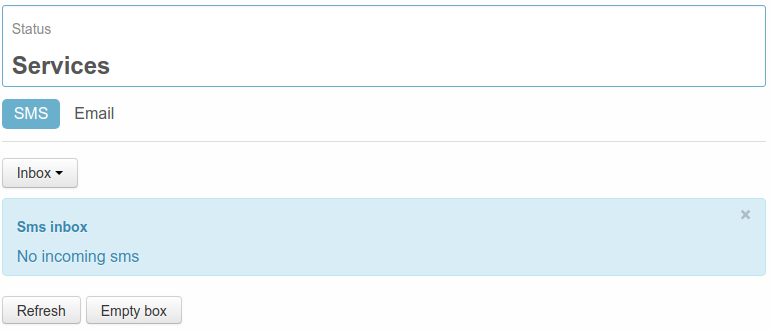
All sent and received SMS can be displayed on page Status → Services → SMS: the first page to be entered will show the SMS received by the device.

../_images/status_services_sms_inbox2.png

In the table the following information will be available:

  • Number: shows the Phone number of the SMS sender
  • Reception date: displays the date and time when the WE200 has received the message
  • Text: contains the text of the received message

The button Refresh can be clicked at any time in order to update all information; Empty box for deleting all messages stored on Inbox.

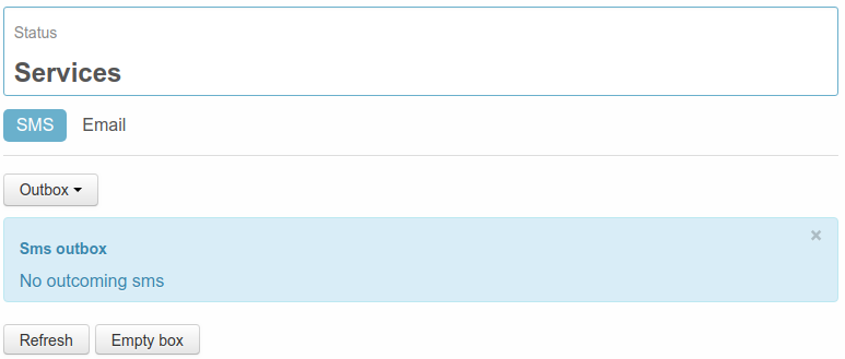
Clicking on the drop-down menu on the top of the table, it’s possible to pass from Inbox to Outbox.

../_images/status_services_sms_outbox2.png

On this table is possible to display all the messages not yet delivered by the WE200. The available information are the following:

  • Number: refers to the phone number of the message receiver
  • Creation date: shows the date and time when the message has been created
  • Text: displays the text of the message

The button Refresh can be clicked at any time in order to update all information; Empty box for deleting all messages available on Outbox (such messages won’t be delivered).

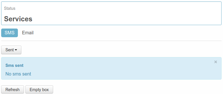
Clicking on the drop-down menu on the top of the table, it’s possible to pass from Outbox to Sent.

On this table are displayed some information regarding the SMS already delivered by the WE200:

../_images/status_services_sms_sent2.png
  • Number: shows the receiver of the delivered messages
  • Send date: displays the date and time when the WE200 has delivered the message
  • Text: contains the text of the sent messages

The button Refresh can be clicked at any time in order to update all information; Empty box for deleting all messages stored on Sent.

3.1.2. LAN connection

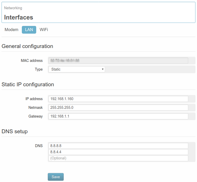
On the page Networking → Interfaces → LAN it’s possible to modify all parameters of the Ethernet interface.

First of all the MAC address of the device will be displayed, with the option of using the LAN network on static IP address or on DHCP.

If the Static address will be selected, the following parameters must be set for the correct operation of the service:

  • IP address static IP address assigned to the WE200. Make sure that the address is available and not used on other devices.
  • Netmask Subnet mask. A valid netmask must be entered, according to the specifications of the own local LAN.
  • Gateway Network gateway
  • DNS DNS that can be assigned to the WE200 ( max. 3)
../_images/interfaces_lan.png

After settings modification the WE200 requires a reboot in order to activate them. If the entered parameters are correct, it’s possible to enter the web interface of the WE200 (even remotely if the network allows it), to send emails and send data to a Portal/Server.

Further information regarding the status of the connection can be found on page Diagnostics → Networking (8.2. Information of connectivity)

3.1.3. Wi-Fi connection

The page Networking → Interfaces → WiFi is available only if, at order confirmation, the option Wi-Fi on USB Port has been selected.
In this case it’s possible to configure the WE200 in order to let it connect to an existing Wi-Fi network.
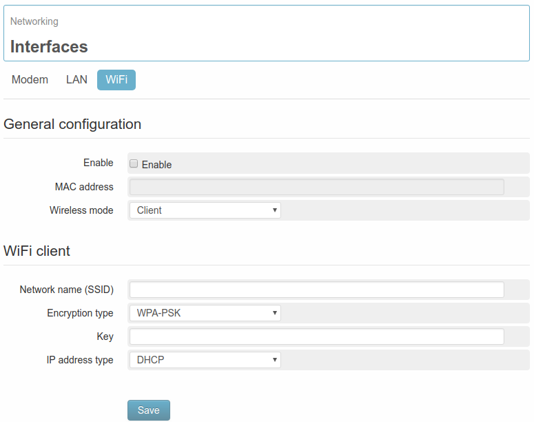
../_images/interfaces_wlan2.png

First of all it will be displayed the MAC address of the Wi-Fi device connected to the WE200, then the access data of the Wi-Fi network where the WE200 has to get connected to, have to be defined:

  • Network name SSID: Complete name of the Wi-Fi network
  • Encryption type: Encryption of the access key
  • Key: type of key/password for the authentication

It will also be given the possibility to choose between a static or dynamic Ip address in the field IP address type. Choosing the static IP address, all necessary parameters for a proper functioning of the service will be required:

  • IP address: static IP address assigned to the WE200. Make sure that the address is available and not used on other devices.
  • Netmask: Subnet mask. A valid netmask must be entered, according to the specifications of the own local LAN.
  • Gateway: Network gateway

After clicking on Save, the WE200 starts to scan the on-site available Wi-Fi networks. Once found the network with the previously set SSID, the WE200 will make the authentication using the indicated parameters.

If all operations will be successful executed, the indicators on the status panel will become green.

The WLAN network allows all operations permitted by the LAN network (remote access to the web server, data sending, email sending).

For further information regarding the status of the LAN connection, it’s possible to enter the page Diagnostics → Networking on section WLAN Interface (see 8.2. Information of connectivity).

3.2. Network services

The menu section Networking → Services allows to enable some additional services, that use the connectivity of the device:

  • Email
  • VPN
  • DNS

3.2.1. Email

Before proceeding with the configuration of the WE200, it’s necessary to make the following:

  • After the selection of the provider (Gmail, Yahoo, Hotmail etc..) enter the provider’s site and create a new valid mail account
  • In the site of the provider, collect all information regarding the parameters to be entered in order to configure the mail service

Once a new account has been created, it’s possible to proceed with the configuration of the WE200, enabling the outgoing emails, the incoming emails or both of them from the page Networking → Services → Email.

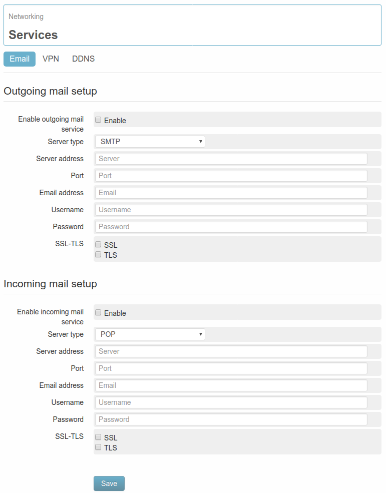
../_images/networking_email4.png

On the section Outgoing mail setup the parameters required for the email sending from the WE200 must be set:

  • Enable outgoing mail service it enables/disables the email sending service.
  • Server type it allows to choose the type of mail server (at the moment only SMTP available)
  • Server address it’s the address of the mail server ( for example smtp.gmail.com)
  • Port it’s the number of the access port (for example 587)
  • Email address the email address associated to the WE200. This will be the address visualized by the receivers of the emails.
  • Username It’s the username of the mail account associated to the WE200.
  • Password It’s the password of the mail account associated to the WE200.
  • SSL-TLS Encryption

Once clicked on the button Save, a new section, called Outgoing mail test, will appear on the bottom of the page: from this section it’s possible to send a test email to any address.

On the section Incoming mail setup the parameters required for the email sending from the WE200 must be set:

  • Enable incoming mail service: Enables/disables the email receiving service.
  • Server Type: Type of mail server (at the moment only POP available)
  • Server address: the address of the mail server (for example pop.gmail.com)
  • Port: Number of the access port (for example 995)
  • Email address: the email address associated to the WE200. The commands sent by the authorized users should be sent to this address.
  • Username: It’s the username of the mail account associated to the WE200.
  • Password: It’s he password of the mail account associated to the WE200.
  • SSL-TLS: Encryption

A properly configured mail service allows the authorized users to send commands to the WE200 (see 7. Commands)

All sent and received emails can be visualized on the page Status → Services → Email.

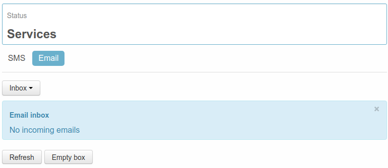
The first page shows the emails received by the device:

../_images/status_services_email_inbox4.png

On the displayed table the following information are available:

  • Mail address: the mail address of the sender
  • Reception date: Date and time when the WE200 received the email.
  • Text: text of the received email.

At any time it’s possible to click on the button Refresh in order to update the information, or Empty box, in order to delete all messages available inside Inbox.

Clicking on the drop-down menu on top of the table, it’s possible to pass from Inbox to Outbox.

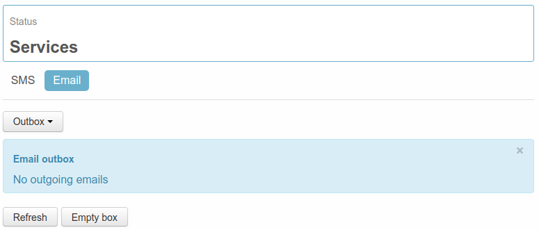
../_images/status_services_email_outbox4.png

On this table it’s possible to visualize all the emails not yet delivered by the WE200. The following information will be shown:

  • Mail address: in this filed is shown the address of the receiver of the mail.
  • Creation date: It’s the date and time of the mail creation
  • Attempts: it shows the sending attempts made by WE200
  • Text: it displays the text of the mail

At any time it’s possible to click on the button Refresh in order to update the information, or Empty box, in order to delete all messages available inside Outbox ( deleted mails won’t be sent out)

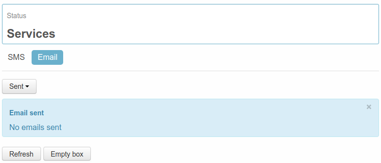
Clicking on the drop-down menu on top of the table, it’s possible to pass from Outbox to Sent. On this table are displayed some information referred to the email already sent by the WE200:

../_images/status_services_email_sent4.png
  • Mail address: in this filed is shown the address of the receiver of the mail.
  • Creation date: It’s the date and time of the mail delivery
  • Attempts: it shows the sending attempts made by WE200 before the successful delivery
  • Text: it displays the text of the sent mail

At any time it’s possible to click on the button Refresh in order to update the information, or Empty box, in order to delete all messages available inside Sent.

3.2.2. VPN

From the page Networking → Services → VPN it’s possible to enable the VPN service to Nethix Portal or to a corporate VPN server.

It’s possible to enable the VPN according to two modes:

  • Auto
  • Manual

The automatic VPN is used to build up a secure connection to Nethix Portal. The automatic VPN allows also to build up a secure and encrypted connection between a PC and the device.

For further information about the use and the advantages granted by the VPN service, see the relevant manual manual.

On the other hand the manual VPN is used to build up a secure connection to a external VPN service, compatible with OpenVPN clients.

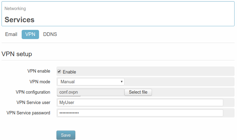
../_images/vpn_manual4.png

The parameters to be configured in order to enable a manual VPN are the following:

  • VPN mode: modality of the VPN, in this case: Manual
  • VPN configuration: this is the configuration file, released by the selected VPN Service Provider
  • VPN Service user: the username for authenticating on the VPN service
  • VPN Service password: the password for authenticating on the VPN service

3.2.3. DDNS

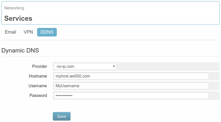
The WE200 offers also the possibility of associating the connection with a dynamic DNS service, choosing from the List of Providers available on page Networking → Services → DDNS.

../_images/we200_sw_networking_services_ddns.png

This service allows to access the WE200 even if no static IP is available, since the device will be identified by the selected provider at every single connection, allowing the users to reach the web interface, just entering the hostname as configured on the browser. For further information see the Provider’s site or contact Nethix Support.

3.3. NAT and Port Forwarding

From the section Networking → Routing it’s possible to enable the NAT function and set the rules for the port forwarding.

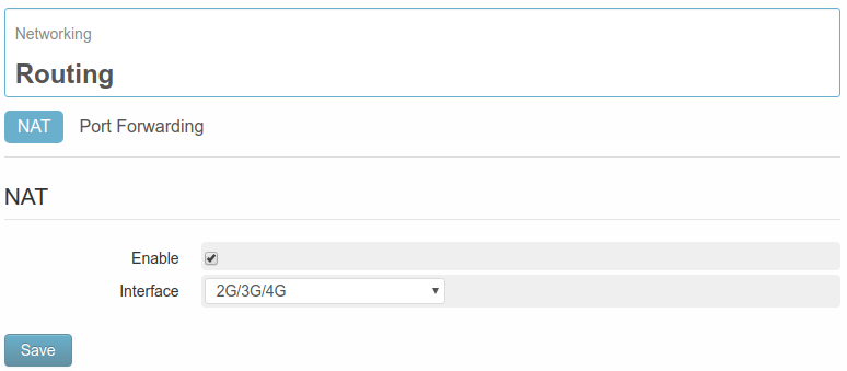
NAT function is available on page Networking → Routing → NAT

../_images/nat.png

Enabling the function NAT, the device will run in gateway mode, i.e. it will provide connectivity through the interface, selected by the connected devices.

../_images/nat_example.png

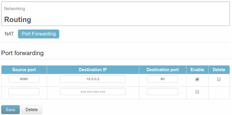
Port Forwarding function is available on page Networking → Routing → Port Forwarding

../_images/port_forwarding.png

Setting the routing rules it’s possible to forward to a defined IP address and port, the traffic coming to the WE200.

For instance:

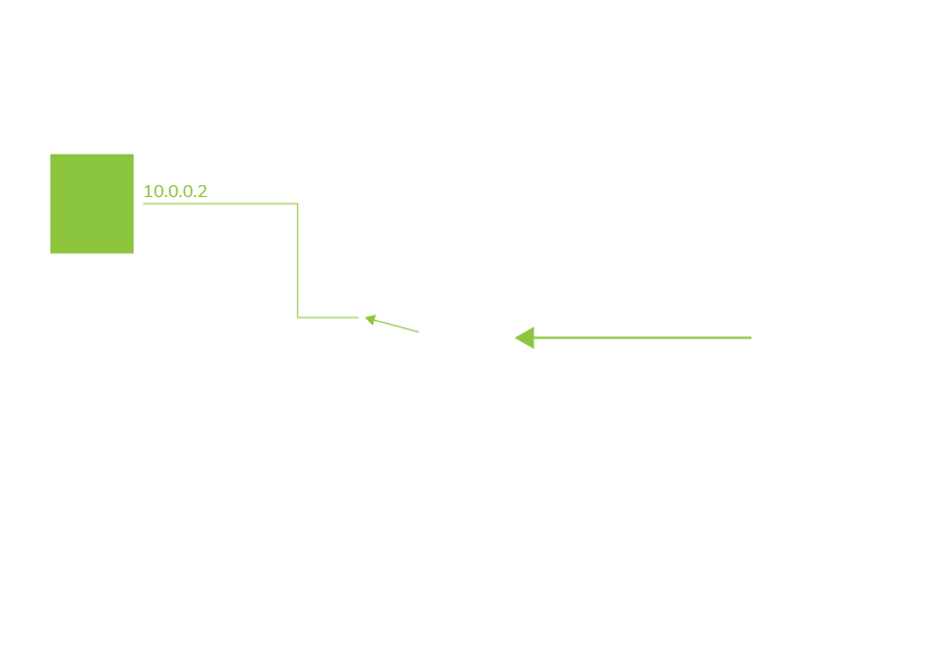
WE200 is inside a LAN network and has the local IP address 10.0.0.1 and the public IP address 1.2.3.4 (for entering Internet). It is necessary to reach the port 80 of another device (connected with WE200) having local IP address 10.0.0.2. It’s possible to set the following rule:

  • Source port: 8080
  • Destination IP: 10.0.0.2
  • Destination port: 80

According to this rule, by typing 1.2.3.4:8080 in the address bar of your Internet browser, you will be redirected to the port 80 of the device having IP 10.0.0.2.


4. I/O

WE200 includes 1 digital input and 1 digital output which can be used for general purposes, i.e. send notifications to the users or turn on/turn off electrical devices.

4.1. Digital Input

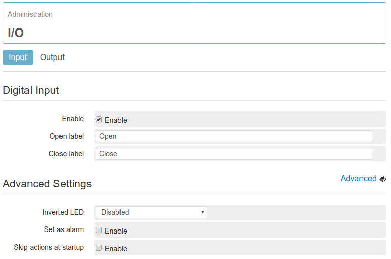
In order to configure the on-board digital input it’s necessary to enter the menu page Administration → I/O → Input.

../_images/di2.png

First of all is requested to complete the fields Close label and Open label. Close label refers to the value (or status), that will be displayed when the digital input is closed, Open label refers to the open input. For WE200 a closed Digital Input variable has a logic value of 1. In case of an open input, the logic value is 0. This becomes a very important information for the definition and setting of the events.

There are some advanced parameters, that can be entered clicking on the option Advanced:

  • Inverted LED This can change the visualization of the variable on the page Status → Variables Status. If this option is disabled, the open status of the input will be associated to a grey spot, while the closed status to a green one. With enabled option, the situation will be the opposite.
  • Set as alarm With this option enabled, at the occurrence of the event, a red ”X” will be displayed near the name of the relevant variable on the page Status → Variables status, to indicate the presence of a critical condition.
  • Skip actions at startup If an event has been defined on the digital input, and at the reboot of the system the digital input is in alarm status, through this optional function no action will be enabled.

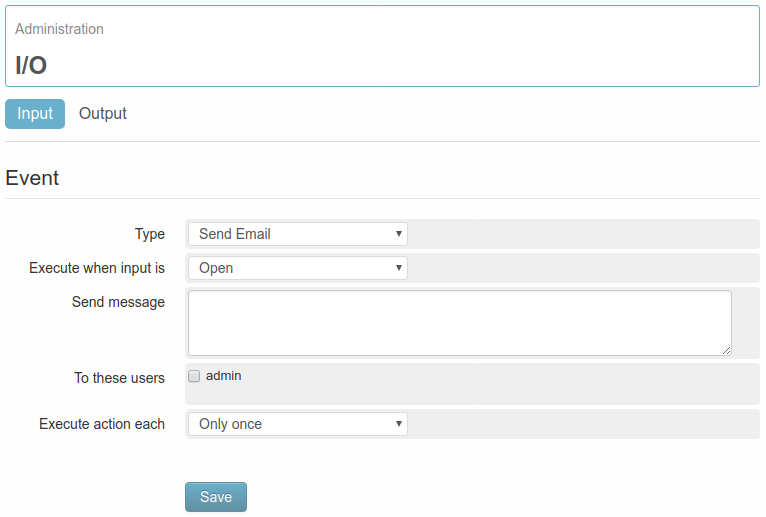
Clicking on Add event link a new page will be entered. From this page it’s possible to enter the text to be sent via SMS or Email in case of status change of the digital input.

../_images/event_di.png

From the field Type it’s possible to choose between Send Email and Send SMS options. The following fields do not depend from the selection made previously.

  • Execute when input is Allows to decide whether the text has to be sent when the input closes or opens
  • Send message Allows to define the text to be sent
  • To these user Allows to select the users that should receive this message
  • Execute action each Allows to decide if the message sending has to be made only once or at regular interval until the current condition remains valid

After definition of the event and action that generate the SMS to be sent to a defined user, some more conditions are necessary:

After definition of the event and action that generate the email to be sent to a defined user, some more conditions are necessary:

  • Availability of a LAN or GPRS/HSPA/LTE connection (see section 3. Connectivity and 8.3. Ping)
  • The configured user/s should be enabled to receive notifications emails at a valid email address ( see 5. Users)
  • The mail service must be properly configured (see 3.2.1. Email)

4.2. Digital Output

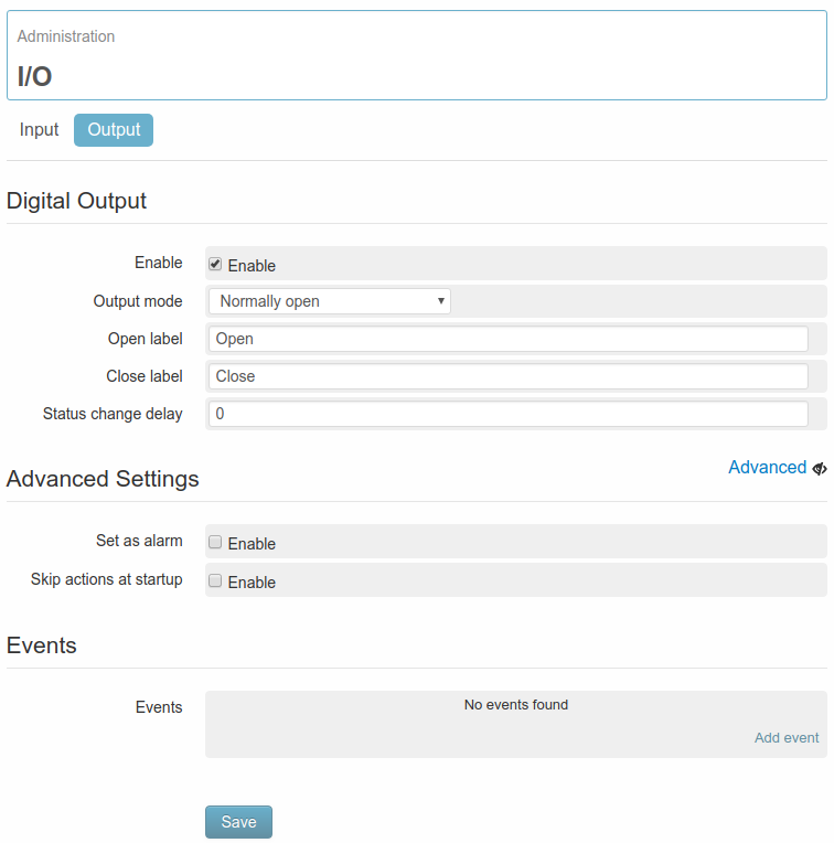
In order to configure the on-board digital output it’s necessary to enter the menu page Administration → I/O → Output.

../_images/do.png

It’s required to set the operating mode in the Output mode field. The available options are:

  • Normally open: The output is normally open. Open label refers to the open status of the contact. Close label will close the contact.
  • Normally closed: The output is normally closed. Open label refers to the open status of the contact. Close label will close the contact.
  • Pulse open: The output operates in pulse mode. Open label refers to the open status of the contact. Close label will close the contact. Once closed, the outputs keeps this status for the time configured on the field Pulse duration, after that it returns automatically to the open status.
  • Pulse closed: The output operates in pulse mode. Open label refers to the open status of the contact. Close label will close the contact. Once opened, the outputs keeps this status for the time configured on the field Pulse duration, after that it returns automatically to the closed status.

Regardless of the selected option, the field Status change delay(s) must be filled in with the number of seconds of delay required between an impulse and the enabling/disabling of the output.

There are some advanced parameters, that can be entered clicking on the option Advanced:

  • Set as alarm With this option enabled, at the occurrence of the event, a red ”X” will be displayed near the name of the relevant variable on the page Status → Variables status, to indicate the presence of a critical condition.
  • Skip actions at startup If an event has been defined on the digital output, and at the reboot of the system the digital output is in alarm status, through this optional function no action will be enabled.

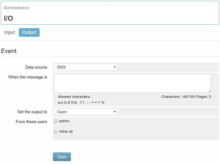
Clicking on Add event link a new page will be entered. From this page it’s possible to enter the text to be sent via SMS or Email to change the digital output status.

../_images/event_do.png

From the field Data source it’s possible to choose between Email and SMS options. The following fields do not depend from the selection made previously.

  • When the message is Allows to decide the text that has to be sent from a user to change the digital output status
  • Set the output to It allows to define the status that the output will have to assume once the command has been received
  • From these users Allows to select the users enabled to send the message

After definition of the event, some more conditions are necessary:

SMS

Email

  • Availability of a LAN or HSPA/LTE connection (see section 3. Connectivity and 8.3. Ping)
  • The configured user/s should be enabled to send email commands from a valid email address ( see 5. Users)
  • The mail service must be properly configured (see 3.2.1. Email)

4.3. Variables status

The page Status → Variables Status contains and displays both variables listed in alphabetical order:

../_images/var_status.png

The table with all variables is divided into 6 columns:

  • Name: Name of variable
  • Value: Numeric or mnemonic value of variable.
  • Unit: Displays the measurement unit assigned to the variable. For the variables with no measurement unit the column will remain void.
  • Set: Allows to set a value ( or status) to the digital output.
  • Status: An icon showing the status of the Digital Input variable will be displayed: green status_on or gray status_off , according to the status and configuration of the variable.
  • Alarm: There’s a column that shows the alarm status of a variable. The icon ok indicates that no active alarms are available. The icon not_ok indicates on the other hand the presence of an event configured as an alarm.
The page Status → Variables Status is automatically refreshed every 5 seconds. It’s therefore possible to display possible status variations without refreshing the page manually.


5. Users

In order to enter the device web interface and to receive/send SMS and Mail, it’s necessary to define the users.

Three different types of users are available: SYSTEM, ADMIN and USER. The main features of each user’s level are the following:

  • SYSTEM
    • Can read, edit, create and delete all other users
    • Is the only user that can generate other ADMIN users.
    • Is the only user that cannot be deleted. Only logging with SYSTEM credential is possible to change all parameters of this user (username and password included) but not delete its account
    • Can access all system’s functionalities.
  • ADMIN
    • Can read, edit, create and delete users of USER type
    • Cannot delete itself, but can change its own parameters
    • The SYSTEM user can set an expiry date for stopping the device’s access to the ADMIN user.
    • Can access all system’s functionalities, as the SYSTEM user.
  • USER
    • Cannot read, edit, create nor delete any type of users.
    • Can change only its own parameters (but not delete itself)
    • Can access the sub-menu Status, but cannot configure the system nor create/edit/delete variables and events.
    • The SYSTEM user and the ADMIN users can set an expiry date for stopping the device’s access to the USER user
    • Cannot reboot nor switch off the device.

Originally the default user is a System Administrator type SYSTEM, whose credentials for access are the following (it’s recommended to change these credentials as soon as possible):

Username: admin

Password: admin

5.1. How to create a new user

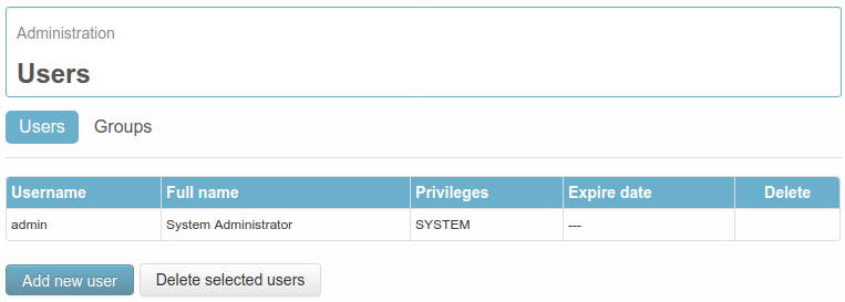
It’s possible to create a new user from page Administration → Users → Users.

../_images/users_get_all4.png

On this page some information regarding the previously created users are displayed:

  • Username: the username to login
  • Full name: the complete name assigned to the user
  • Privileges: the authorization level of the user (SYSTEM, ADMIN o USER)
  • Expire date: the expiry date for user’s deactivation (not deletion)
  • Delete: selection of the users to be deleted through the tab Delete selected users

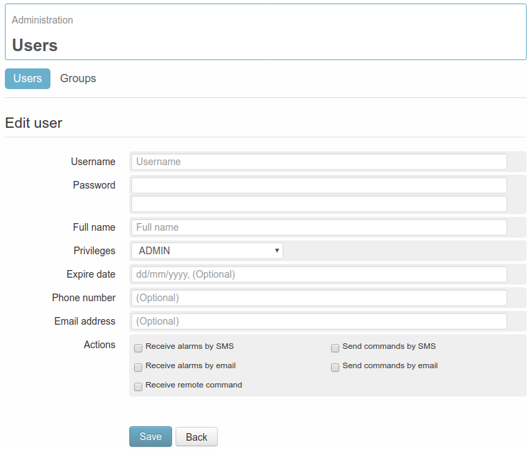
To edit an existing user just click on its username, to generate a new one click on Add new user.

../_images/users_create4.png

The parameters to be set in order to create a user are the following:

  • Username: the username to login
  • Password: the password to be used for login (to be entered twice). The password can be composed of alphanumeric characters and special characters. Being case sensitive, it’s necessary to pay attention to upper and lower cases.
  • Full name: the complete name assigned to the user. After the login, the Full name will be displayed on the top left corner, near the name assigned to the WE200. Clicking on it, the user configuration page is entered.
  • Privileges: the authorization level to be assigned to the customer, among SYSTEM, ADMIN e USER (5. Users)
  • Expire date: Allows to set a deadline after which the user cannot access the interface nor send/receive commands or notifications from/to the WE200. If no expiry date is required this field must be left blank.
  • Phone number: Telephone number associated to the user. It’s necessary if the user wants to send/receive SMS from/to the device, on the contrary it can be left blank.
  • Email address: Email address associated to the user. It’s necessary if the user wants to send/receive email to/from the device, on the contrary it can be left blank.
  • Actions: in this section it’s possible to enable/disable all options connected to the user:
    • Receive alarms by SMS: if enabled, it allows the user to receive SMS alarms from the WE200, if previously configured.
    • Receive alarms by email: if enabled, it allows the user to receive email alarms from the WE200, if previously configured.
    • Send commands by SMS: if enabled, it allows the user to send commands to a WE200 via SMS
    • Send commands by email: if enabled, it allows the user to send commands to a WE200 via mail.
    • Receive remote command: if enabled, any message sent by the WE200 to the selected user won’t bear the name of the WE200 on the object. This allows to send Set/Get commands between devices.

5.2. Users group

If the system has a high number of users, the management of events and actions might become complex. In order to help managing this situation, it’s possible to create groups of users.

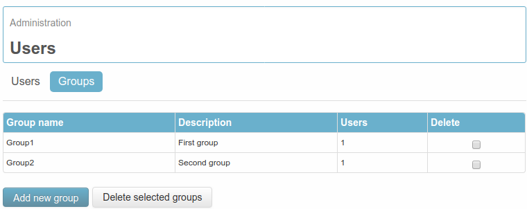
For creating, deleting and editing the groups of users, it’s necessary to go to page Administration → Users → Groups.

../_images/groups_get_all4.png

On this page it’s possible to read the information regarding the previously created groups, as for example:

  • Group name: the name assigned to the group
  • Description: the description of the group in object
  • Users: The number of users available in the group
  • Delete: selection of the groups to be deleted through the tab Delete selected groups.

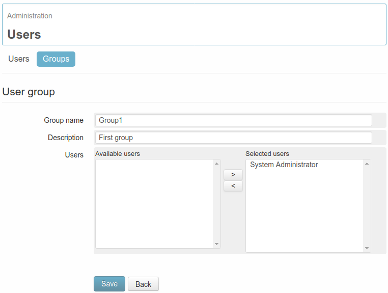
To edit an existing group just click on its name, to generate a new one click on Add new group.

../_images/groups_create4.png

For the proper creation of a new group only few information are necessary:

  • Group name: the name assigned to the group
  • Description: the description of the group in object
  • Users: this field allows to select the users to be included in the group. After the selection with the mouse from the box Available users, just click > to include them in the box Selected users or < to exclude them from the group.

Clicking Save, the group will be created. Here are some remarks referred to the groups of users:

  • A user can be assigned to any group
  • A user can belong to more than one group (even to all groups)
  • Since the WE200 can recognize repeated numbers or email addresses, even if a user is registered in more than one group, it will receive only one notification.
  • Deleting a group of users, the single users previously assigned to the group won’t be deleted.

6. System operation

6.1. System settings

On section Administration → General Setup it’s possible to define some general settings of the device.

6.1.1. Information about the system

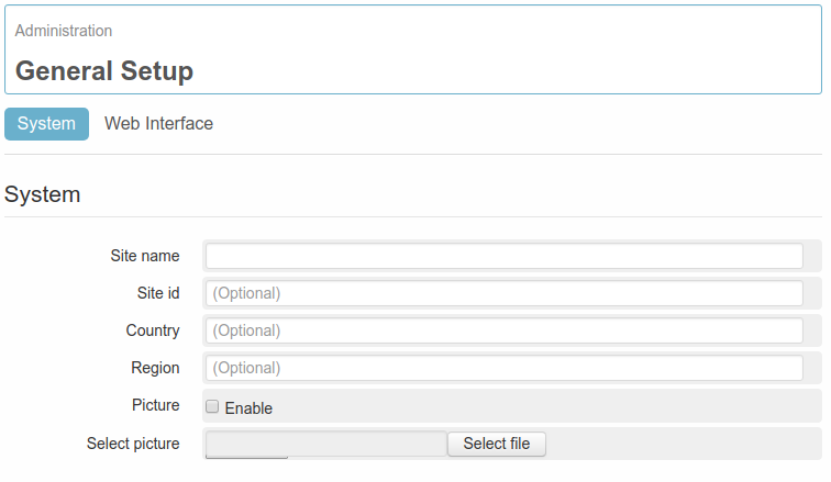
On the page Administration → General Setup → System, under the section System, it’s possible to configure the contents to be displayed on the page Status → Site immediately after the login. These parameters are not compulsory and are used just to identify the device.

../_images/general_setup_system_system4.png
  • Site name: the name assigned to the device
  • Site id: numeric ID assigned to the device
  • Country: Country where the device is installed
  • Region: Region/Area where the device is installed
  • Picture: when this option is enabled, it’s possible to select an image, by clicking on Select picture, and then display the selected image after the login (for example the picture of the installation, of the company..and so on..). The picture will be displayed on the page Status -> Site.

6.1.2. Date and time

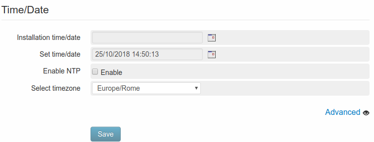
On the page Administration → General Setup → System**under the section **Time/Date, it’s possible to set the date and time of the device:

../_images/general_setup_system_time_date4.png
  • Installation time/date: It states the date and time, when the device has been installed. This information has no influence on the functioning and has the only reason of identifying the installation.
  • Set time/date: It allows to set the date and time of the device.
  • Enable NTP: it enables the automatic synchronization of time. Once per day and at every reboot, the WE200 will connect to the server in order to update date and time precisely, according to the relevant timezone.
  • Select time-zone: it allows to set the timezone of the device.

It is also possible to specify a custom NTP server, by clicking the Advanced link.

6.1.3. Web interface personalization

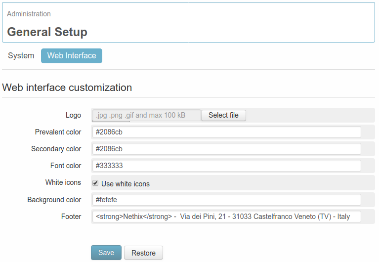
Some graphical personalizations of the web interface of the device are possible from page Administration → General Setup → Web Interface, and will be valid for all the users.

../_images/general_setup_web_interface4.png
  • Logo: this allows to choose an image to replace the Nethix logo on the left top of the page.
  • Prevalent color: Primary color of the page. (RGB hexadecimal color, for example: #007BC5)
  • Secondary color: Secondary color of the page. (RGB Hexadecimal color, for example #009FE9)
  • Font color: Color of the text. (RGB Hexadecimal color, for example #007BC5)
  • White icons: Disabling this option, all the icons of the header (power-off, reboot, logout) will be displayed in black.
  • Background color: Color of page’s background .(RGB Hexadecimal color for example #007BC5 )
  • Footer: it allows to configure the footer at convenience (HTML code is allowed)

Clicking on all colored fields, a color picker will allow to select the desired color and automatically insert the relevant hexadecimal value.

6.2. System information

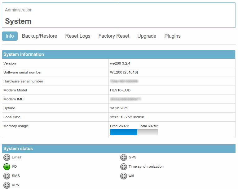
On page Administration → System → Info it’s possible to find some additional information regarding the WE200. On section System Information are displayed some general information:

../_images/system_info1.png
  • Version: it’s the version currently installed on the device.
  • Software serial number: it’s the serial number available on the backside label of the device.
  • Hardware serial number: it’s the hardware serial number, that is important for registering on the portal for using services as the VPN by Nethix.
  • Modem Model it’s the model of the Modem inside the WE200.
  • Modem IMEI: it’s the IMEI code of the Modem inside the WE200.
  • Uptime: it’s the operating time of the WE200 from the last start.
  • Local time: date and time of the device
  • Memory usage: it’s the status of the RAM memory.

On the section System Status, the status of some other services and functions of the device is shown. Beside every single service is available a graphic indicator, that allows to have a quick overview of the WE200 status.

Generally speaking, a green indicator means that the service is enabled and properly functioning, while a grey indicator means that the service is disabled and the red indicator, that the service is not properly configured and not in use. Clicking on any indicator, it’s possible to access the configuration section of the relevant service.

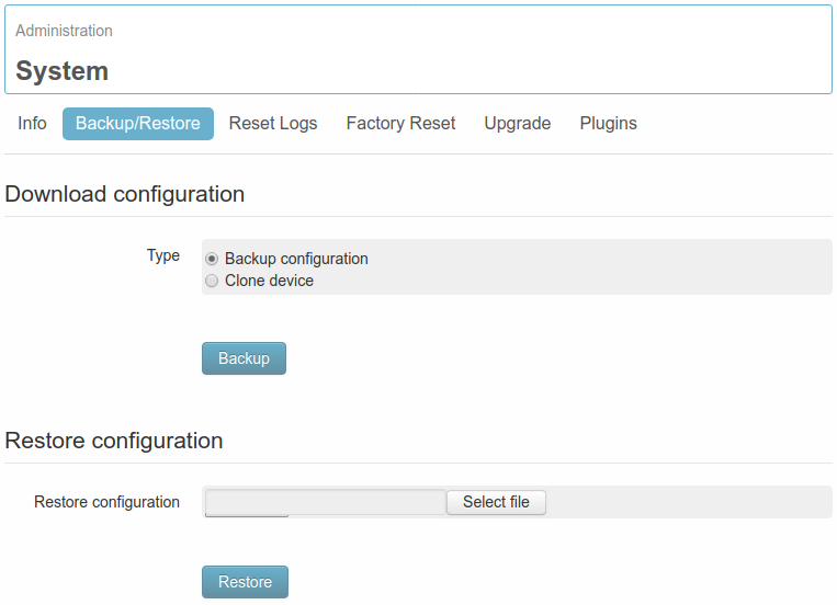
6.3. Backup/Restore function

WE200 offers the possibility to make a backup of the device configuration as an encrypted file on page Administration → System → Backup/Restore.

../_images/system_backup_restore4.png

The backup includes:

  • I/O configuration
  • Associated events and actions
  • Networking settings
  • Created users
  • Enabling and configuration of the services

Not included in the backup:

  • System log
  • Service log
  • SMS/Email/Cloud archives

To make the backup, click on Backup.

Once received the encrypted backup file, it’s possible to load it on any other device in line with the first one.

From the section Restore configuration, select the encrypted backup file and click on Restore. After this operation, it’s recommended to reboot the device, in order to make the modification effective.

The Backup/Restore function can be useful to keep a copy of the configuration made, in order to reload it on the device itself or on some more additional devices having the same configuration.

In this last case (Restore on additional WE200) the devices must have the same Firmware version. If not, please contact Nethix support.

6.4. Delete log

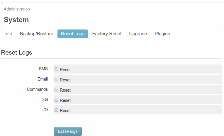
The internal memory of the WE200 allows to store a huge number of logs. But to avoid an overloading of the device, it’s possible to delete any logs from the page Administration → System → Reset Logs.

../_images/system_reset_logs.png

The Logs that can be deleted are the following:

  • SMS: it deletes all available SMS (sent, received and outgoing)
  • Email: it deletes all available emails (sent, received and outgoing)
  • Commands: it deletes all the logs referred to the execute a command.
  • I/O: it deletes all the I/O logs.

Once selected one or more of above listed positions, click on Erase logs for deleting permanently the logs from the device memory.

6.5. Factory reset

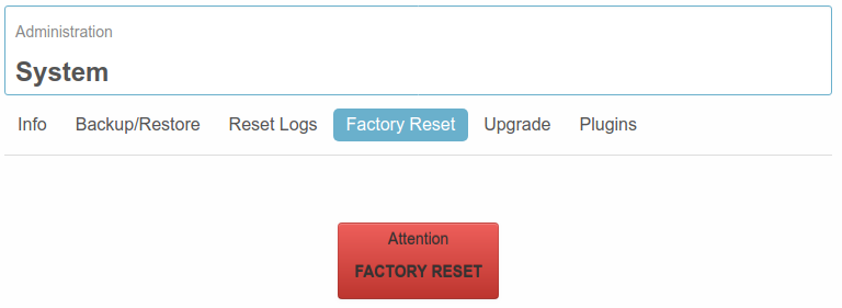
From the page Administration → System → Factory Reset it’s possible to delete all stored logs and data and reset the configuration, bringing the device back to the factory settings.

../_images/system_factory_reset5.png

Click the big red button on the page, and confirm the choice. After the confirmation the WE200 will reboot and after the initialization phase the device will be again accessible via LAN.

6.6. Device upgrade

The WE200 can be upgraded any time upon customer’s request or on suggestion of Nethix.

The upgrading can be made in two different ways: * downloading the updated version from the official Nethix Server (after having contacted Nethix Support) * uploading on the device an encrypted file, containing the upgrade (to be requested at Nethix Support).

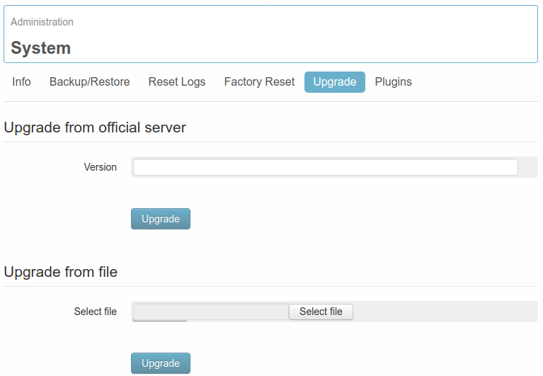
Both procedures are available on page Administration → System → Upgrade.

../_images/system_upgrade4.png

On section Upgrade from official server it’s possible to enter the name and number of the version to be downloaded, and get it directly from the Nethix Server. In order to know the Name and Firmware version number to be installed on the device, it’s necessary to contact Nethix Support.

Once received the string, enter it in the field Version and then click on Upgrade.

The download time depends from the connection speed available with the WE200. Once downloaded the version, the WE200 will restart in order to proceed with the installation. This operation could require about 5 minutes.

Once the WE200 has returned to be available, it’s recommended to enter the interface in order to check the result of the upgrading operation (on the status panel).

On the other hand, from the section Upgrade from file, it’s possible to send to the WE200 an encrypted package, containing the upgrade, after having downloaded it on the PC.

The package changes according to the starting version to be upgraded, it therefore must be required directly at Nethix’s support.

To start the upgrading it’s required to select the file to be sent and click the relevant button Upgrade. Once the file has been sent to the device, the WE200 will restart in order to proceed with the installation of the new version.

The download time depends directly from the speed of the active connection available with the WE200. Once downloaded the version, the WE200 will restart in order to proceed with the installation. This operation could require about 5 minutes.

Once the WE200 has returned to be available, it’s recommended to enter the interface in order to check the result of the upgrading operation (on the status panel).

6.7. Plugins

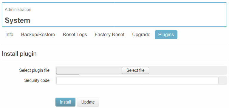
The plugins are encrypted packs, that allow to add or change part of the configuration and some of the available web pages.

To load a new plugin or to check the list of the already installed plugins on a device, go to page Administration → System → Plugins.

../_images/system_plugins4.png

The plugin tool allows, for example, to send a package to a WE200, in order to add a pre-set configuration according to the specifications or requirements of the customer.

Through a plugin it’s possible to add:

  • Variables
  • Formulas
  • Events and actions
  • Customized pages, or dedicated to a specific application

The main difference between a plugin and a backup restore, is that through the plugins some additional pages can be created and added, and that also new additional variables, events or actions can be introduced beside those already existing (with the restore function the configuration is only overwritten).

To know the available plugins or to request additional customized plugins, it’s necessary to contact Nethix’s Support.


7. Commands

The WE200 has a list of preconfigured commands, that allow to set or to read some system parameters. Commands can be sent by any authorized user, both via SMS and via mail. On the table below are listed all system commands with relevant description:

Command Description
STAT

Request of the system status. The device answers sending an SMS or Mail, containing following information:

  • IP address (HSPA/LTE if available, or LAN)
  • Uptime of the device
  • CPU load

Example:

IP:192.168.1.146 (15:54:49 UP 9 DAYS, 7:07, load average: 0.32, 0.23, 0.18)

WAKEUP

Request of a HSPA/LTE On-Demand connection.

When the WE200 receives this command (SMS or Mail) from an authorized user, if the HSPA/LTE connection is On-Demand, it will establish a new connection, which remains on for 15 minutes. If no dynamic DNS service is enabled, it’s possible to use the above mentioned STAT command to receive the IP address of the WE200.

SETTIME MMDDhhmmYYYY

When the WE200 receives this command (via SMS or Email) from a registered user, a new date and time, as indicated in the text message, will be set.

The syntax means: MM=month, DD=day, hh=hour, mm=minutes, and YYYY=year

EXAMPLE: For setting the date 6th December 2019 and the time 11:07 send the following message: SETTIME 020611072019

SIGNAL

Request for the GSM Signal strength

When the WE200 receives this command (either via SMS or Email) from a registered user, the device will check the strength of the available GSM signal and will inform the requesting party according to the following format: GSM Signal:XX Where instead of “XX” a number between “01”(no signal) and “31” ( max. signal) will be reported.

ReBooT

Request for a system reboot. When the WE200 receives this command (either via SMS or Email) from a registered user, it will start a system reboot.

Pay attention to upper and lower case letters.

PowerOff

Request for a system power off.

When the WE200 receives this command (either via SMS or Email) from a registered user, it will turn off the system. It will be necessary to disconnect and then reconnect the power in order to let the device start again.


8. Diagnostic

The WE200 offers the possibility to make some diagnostic operations and display some data referred to the system functioning.

Entering the section Diagnostics it’s possible to get some additional information regarding the active connections, in order to check the proper functioning of the same.

8.1. System Log

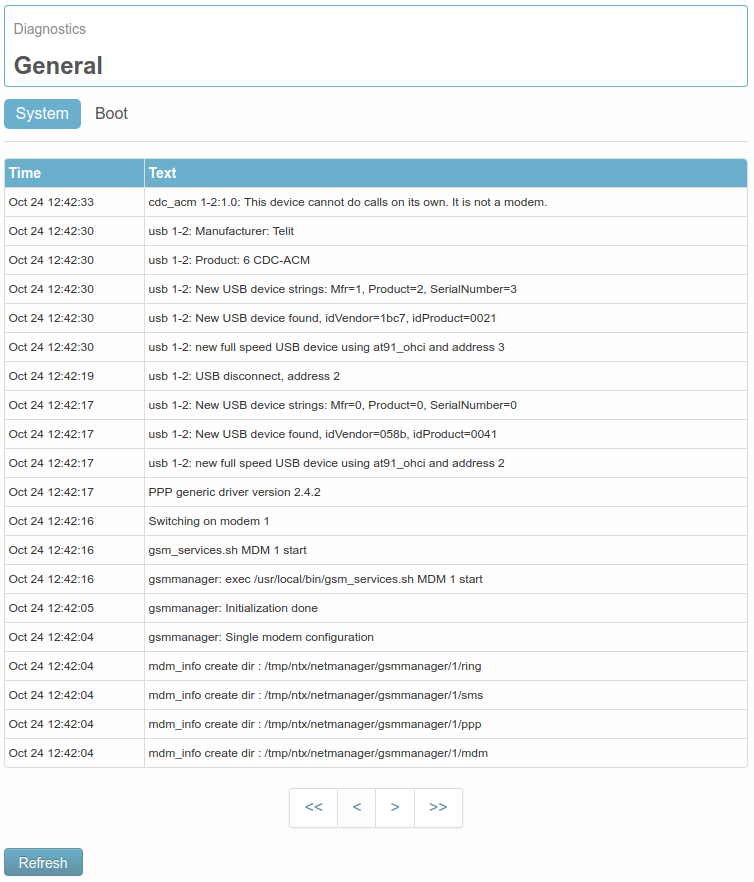
From the page Diagnostics → System → System it’s possible to read the last 20 logs of the system.

../_images/diagnostics_general_system4.png

On the table are displayed some useful information for having a feedback on the system status and for finding possible malfunctions. For updating the list of the displayed logs, click on the button Refresh.

In case of error notifications, check the device configuration and refer to Nethix support for further instructions.

From the page Diagnostics → System → Boot it’s possible to display the logs referred to the system boot, that is the operations executed by the WE200 at every restart/reboot.

../_images/diagnostics_general_boot4.png

Those information can be relevant for Nethix Support in case of technical assistance.

8.2. Information of connectivity

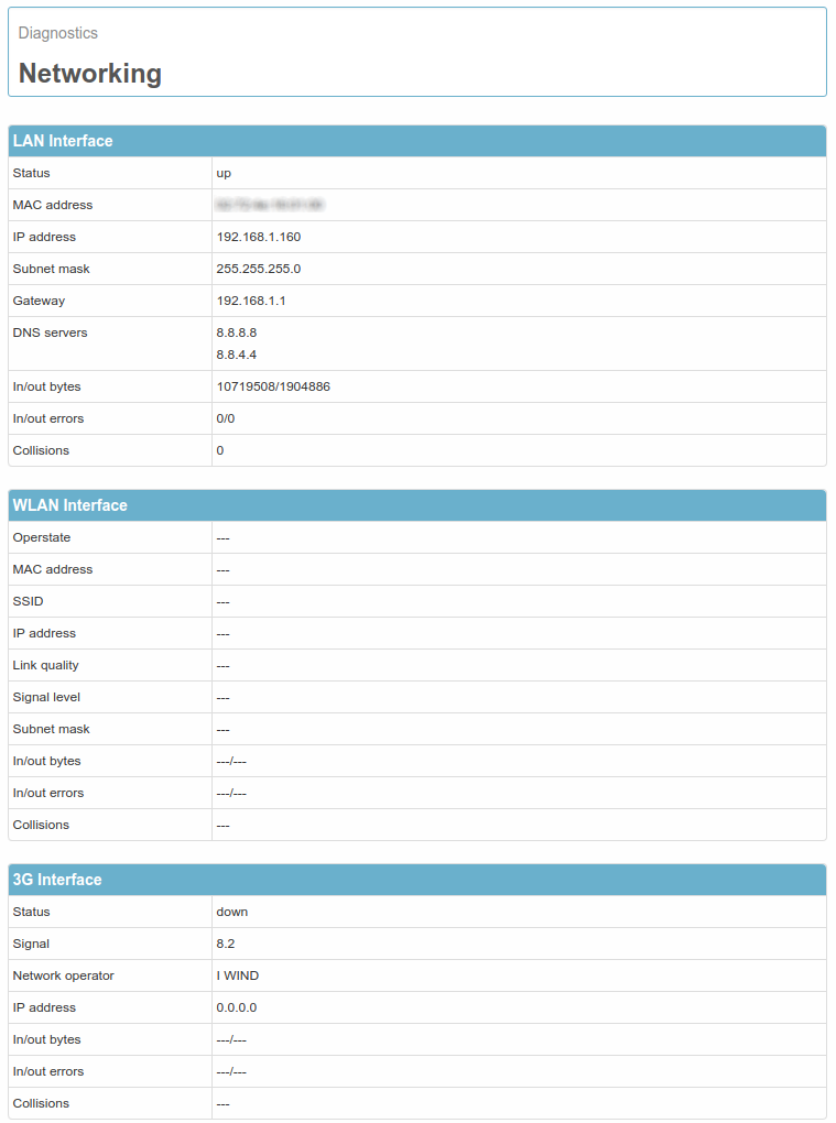
From the page Diagnostics → Networking it’s possible to get additional information regarding the status of the active connections.

../_images/diagnostics_networking.png

The page is divided into three sections: LAN interface, WLAN Interface and 3G(4G) Interface.

Every section reports a number of technical information regarding the relevant connection.

LAN Interface:

  • Status: up if the connection is established, down if the service is not available or if the WE200 has not come to establish a connection.
  • MAC address: it displays the MAC address of the WE200 network interface
  • IP address: previously configured (Static) or acquired (DHCP) IP address
  • Subnet mask: previously configured (static) or acquired (DHCP) subnet mask
  • Gateway: previously configured (static) or acquired (DHCP) gateway.
  • DNS servers: available DNS servers.
  • In/Out bytes: quantity of traffic carried out during current connection.
  • In/Out errors: quantity of outgoing/incoming errors during current connection
  • Collisions: quantity of collisions occurred during current connection.

WLAN Interface:

  • Operstate: up if the connection is established, down if the service is not available or if the WE200 has not come to establish a connection.
  • MAC address: it displays the MAC address of the Wi-Fi device connected to the WE200.
  • SSID: name of the Wi-Fi Network where the WE200 is connected to.
  • IP address: previously configured (Static) or acquired (DHCP) IP address
  • Link Quality: quality of the received signal
  • Signal Level: strength of the signal
  • Subnet mask: previously configured (static) or acquired (DHCP) subnet mask
  • In/Out bytes: quantity of traffic carried out during current connection.
  • In/Out errors: quantity of outgoing/incoming errors during current connection
  • Collisions: quantity of collisions occurred during current connection.

3G(4G) Interface:

  • Status: up if the connection is established, down if the service is not available or if the WE200 has not come to establish a connection.
  • Signal: it gives the signal level in CSQ. The scale ranges from 1 to 31, where 31 is the max. coverage while 1 is the minimum. In order to have a stabilized connection, it’s recommended to have at least a Signal of 15-16.
  • Network operator: it’s the name of the Provider used by the WE200.
  • IP address: IP address of the connection.
  • Gateway: gateway provided by the operator
  • In/out bytes: quantity of traffic carried out during current connection.
  • In/Out errors: quantity of outgoing/incoming errors during current connection
  • Collisions: quantity of collisions occurred during current connection.

8.3. Ping

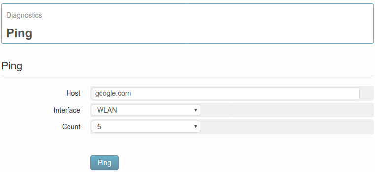
In case of communication problems, for example when sending a mail, the WE200 gives the possibility to run a ping towards any host, allowing the selection of the network interface to be used.

For this operation enter the page Diagnostics → Ping.

../_images/diagnostics_ping.png
  • Host: enter in this field a valid hostname, to be reached through ping (for example www.google.com)
  • Interface: the network interface to be used for reaching the defined host. According to the configuration of the device and enabled services, it’s possible to choose among LAN, 3G/4G and WLAN.
  • Count: it allows to select the ping number to be run.

Once completed above mentioned fields, click on Ping in order to start the operation. The results will be reported on the lower part, allowing the user to find any possible problems arising.


10. Safety guidelines

  • Nethix products support SIM cards from providers of all around the world, particularly from Europe Africa and Asia. However, there could be some incompatible SIM cards.
  • The device cannot receive/send SMS if the SIM card is not enabled to GSM services and network or credit is not available (if prepaid card is used).
  • Verify that the device is operated in an area covered by GSM network with sufficient signal strength for granting proper functioning.
  • In case of questions or doubts regarding the cost of the SMS service consult your Network Provider.
  • This device is only suitable for being installed by a qualified operator
  • Nethix is not responsible for improper use and/or its side effects
  • Nethix products are designed for typical use in industrial automation and/or home applications.

If you plan to use Nethix products in special applications where anomalies and discontinuity of service can have serious effect on human life or can cause physical or material damages, or where extremely high levels of reliability are required (for example in aerospace systems, in atomic energy control systems or n electro-medical devices), please contact Nethix for support to your particular application. Nethix is not responsible of damages caused from its products if such applications are not previously authorized.

not_recyclable The product shall not be treated as household waste. It shall be instead handed over to an appropriate collection point for the recycling of electrical and electronic products. For further information about recycling of this product, contact the local city office and/or the local waste disposal service.


11. Warranty and support

Nethix warrants to the buyer that the product will be defect-free within two years (24 months) from the date of purchase.

During warranty time, and against presentation of purchase invoice, the product will be repaired or replaced, at Nethix’s discretion, without any additional costs as regards spare parts and repair, if the damages are proven to be manufacturing defects.

Warranty will be voided if the product has not been used properly.

In case of technical problems the user can ask for support:


12. Return and repair

Product return to NETHIX must be previously authorized, requesting a RMA number.

Please send an Email at Nethix containing all following information:

  • Complete customer’s name and address
  • Distributor’s or Reseller’s name and address
  • Date of purchase
  • Product P/N and S/N as displayed on the product or the package
  • Detailed description of fault and/or reason for return

Nethix will communicate the RMA number, in order to start the return procedure of the product. The delivery of the goods shall be arranged DDP at Nethix premises. Products returned without factory seals will be automatically treated as out-of-warranty repair services.