User manual

../_images/we120_iso.png

1. Overview

WE120 is a quad band (850/900/1800/1900Mhz) GSM Modem with advanced features for remote control and monitoring, that allows both the standard data communication over the GSM network and the remote activation of electronic devices and systems.

  • WE120 has relay outputs and digital/analogue inputs, that can be set and read sending an SMS from a Smart-phone, a standard GSM mobile phone or a fixed telephone.
  • Can send an SMS to one or more registered users every time an input changes its status or crosses a pre-set threshold.
  • The Relay outputs can also be activated through SMS or voice call (ring).

The WE120 can be easily configured with SMS messages. Thanks to its flexibility the WE120 can be used in several industrial and home applications.


2. Functional characteristics

2.1. GSM modem

The WE120 includes a standard and full featured GSM Modem, that can offer a full set of telecommunication services based n the 3GPP and ITU-T standards:

  • SMS services
  • CSD data communication
  • caller ID

The use and configuration of the Modem are implemented by issuing standard AT commands over its RS232 serial port.

2.2. Remote control

WE120 is a remote control device completely configurable through SMS messaging, App for Android and iOS or the dedicated Software Genesys 3.

It can be configured also through a command line interpreter available at the RS232 input port, that can make the first configuration easier.

The configuration procedure allows to activate the main modes and functions of the device:

  • deend the behaviour of the output relays: level mode (normally open or normally closed) or pulse mode (pulse to close or pulse to open)
  • deend the active status of all the digital inputs: normally open or normally closed
  • activate relay outputs through an SMS
  • activate a relay output through a voice call (ring)
  • program the device to send an unsolicited SMS to one or more pre-set phone numbers, when a digital input changes it status or an analogue signal crosses a pre-set threshold
  • read the status of all digital and analogue inputs /outputs through an SMS on demand
  • periodically receive an SMS with the count value of the inputs, programmed as “counters”
  • use the device as “remote controlled thermostat” in heating and air conditioning systems
  • restrict the use of the device to registered users only, thanks to an internal list of authorized phone numbers and to the “caller ID” feature
  • use passwords for both programming and using the device
  • give a unique name to every WE120 to recognize it in a multi device application.

2.3. I/O expansions

Several I/O Expansion modules are optionally available that can be connected to the WE120 through the Modbus based RS-485 serial port.

Through a proper configuration of the expanded inputs and outputs, it’s possible to operate them as those already included in the device.

The available I/O expanders offer the following possibilities:

  • 16 digital inputs
  • 6 digital inputs and 6 digital outputs
  • 4 analogue inputs
  • 4 temperature inputs (NTC/PT100)

2.4. Diagnostics and firmware upgrade

Diagnostic features are implemented by the device:

  • An SMS message can be automatically sent at device start-up. This feature can be used to monitor power failures.
  • An SMS can be sent periodically to one or more registered use (keep-alive function)
  • The device can read and send to he user the GSM field strength.

The firmware update guide describes how to update the device’s firwmare using the Genesys 3 application.

2.5. Applications

The WE120 can be used in a wide range of applications, including:

  • Home automation
  • Heating and air-conditioning systems
  • Remote control of plants
  • Small residential and industrial automated systems
  • Wireless meter reading
  • Data acquisition
  • Energy saving applications
  • Water treatment plants and remote pumps control
  • Cathodic protection
  • Access control
  • Remote diagnostics
  • Remote activation via SMS

3. Technical characteristics

Characteristics Description
Communciations Quad band GSM 850/900/1800/1900 Mhz embedded Modem, with embedded SIM card reader, and GSM antenna
Mounting DIN bar mountable
Weight 180 gr
Size (L x W x H) 70 x 65 x 90 mm
Storage temperature -25°C - +85°C
Functional temperature -15°C - +55°C
Humidity 0% - 95% (non condensing)
Power source Low tension 9-32VDC/12-24VAC
Consumption Average 100mA, max. peak 250mA
Inputs 4 digital inputs 2 analogue inputs (configurable through Dip SWITCH 0-5V, 0-10V, 0-20mA, NTC)
Outputs 2 outputs 1A 30VDC/230VAC
Ports 1 RS485 serial port, 1 mini B USB port
Output power Classe 4 (2W) for GSM 850 Classe 4 (2W) for E-GSM 900 Classe 1 (1W) for GSM 1800 Classe 1 (1W) for GSM 1900
Reception sensibility higher than -102dBm at antenna connector
Used services RING, SMS, CSD
../_images/we120_connectors.png ../_images/we120_serigrafia.png
Terminal Description
RL1A Relay contact 1
RL1B Relay contact 1
RL2A Relay contact 2
RL2B Relay contact 2
GND Common analogue inputs
AI1 Analogue Input 1
GND Common analogue inputs
AI2 Analogue input 2
DI1 Digital input 1
GND Common digital inputs
DI2 Digital input 2
GND Common digital inputs
DI3 Digital input 3
GND Common digital inputs
DI4 Digital input 4
A RS485 signal A (+)
B RS485 signal A (-)
GND RS485 common/ground
../_images/ac_dc.png Supply, DC positive (+) or AC
../_images/ac_dc.png Supply, DC negative (-) or AC
Electrical Connections
Power Supply

The WE120 can be powered by a DC or an AC supply.

Range:
  • DC: 9V - 32V
  • AC: 12V - 24V
Analog inputs

The analogue inputs can be individually configured in four different modes through the DIP switch

  • 0 - 20 mA
  • 0 - 5 V
  • 0 - 10 V
  • NTC 10K

The standard configuration is:

  • analog input 1: 0 -10 V
  • analog input 2: 0 -20 mA
Digital inputs “dry contact” digital inputs
Relay outputs 1A at 30VDC / 230VAC

Danger

The digital inputs are designed to be operated in low voltage circuits. Avoid direct connection to 230VAC.


4. Installation

This section describes the installation procedure and the first start-up of the WE120.

4.1. Package contents

The package of the WE120 contains:

  • No.1 wireless remote control device WE120
  • No.1 Dual Band Stylus Antenna
  • Quick start guide/ User Manual

A proper power supply unit (for example 24VDC 500mA) and relevant connecting cables are required to operate the device (not included in the supply).

A SIM card enabled to GSM network connection is also required.

4.2. Connections and installation

  • Insert the SIM card in the card holder as described in the following
  • Mount the device on a standard DIN rail, paying attention to the accessibility of the SIM card. Make sure that GSM network is available with sufficient signal (verify with a mobile phone).
  • Connect to the Digital input terminals a dry contact, like a relay, a switch or similar. Do not connect live voltages to avoid damages on the WE120
  • Connect to the RL terminals the load that has to be activated/controlled by the WE120.
  • Connect to the ac_dc terminals the required power source.
  • Insert the GSM antenna

4.3. DIP switch

It’s possible to change the configuration of the analogue inputs through the DIP switch.

../_images/we120_dip_switch.png
  • The switch from 1 to 3 configure the analogue input 1.
  • The switch from 4 to 6 configure the analogue input 2.
  • Switch 7 has to be enabled only in case of Modbus network disturbances.
  • Switch 8 implements a 120Ohm termination resistor on RS485 Port

Setting instructions on following table:

  Analog input 1 Analog input 2
0 - 20mA switch 1: ON, switch 2 and 3: OFF Switch 4 at ON, switch 5 and 6:OFF
0 - 5V Switch 1, 2 and 3: OFF Switch 4, 5 and 6: OFF
0 - 10V Switch 2: ON, switch 1 and 3: OFF Switch 5: ON, switch 4 and 6: OFF
NTC Switch 3: ON, switch 1 and 2: OFF Switch 6: ON, switch 4 and 5: OFF

4.4. SIM card insertion

  • Before the start-up of the WE120, insert the designated SIM Card into a GSM mobile phone in order to disable the PIN code.
  • No further operation is required for the SIM card. It’s not necessary to add contacts on the SIM phone-book, since the WE120 can manage them automatically
  • Lift the upper panel of the WE120 from one side using a screwdriver. Operate carefully and with a thin tool to avoid damages on the plastic case.
  • Unlock the SIM holder connector moving the sliding holder in the direction indicated for OPEN.
  • Lift the sliding holder and insert the SIM in the designated housing, paying attention to the correct positioning of the card.
  • Close the sliding holder to block the connector, moving it in the direction indicated for LOCK.
  • Reinstall the upper panel of the WE120.
../_images/we120_sim.png

4.5. Switching on the WE120

  • Make sure that the WE120 is properly connected, as described above.
  • Supply the system to be monitored
  • Power the WE120
  • The device takes some seconds for the initialization. During this phase the GSM LED blinks fast. After some time the RUN LED is switched on. Initialization ends with a GSM signal check. The LEDs DI1, DI2, DI3, DI4, RL1 and RL2 blink five times showing the signal level, as described below:
    • NO LED blinking: NO GSM signal (*)
    • 1 LED blinking: very low GSM signal (*)
    • 2 LEDS blinking: low GSM signal
    • 3 LEDS blinking: medium GSM signal
    • 4 LEDS blinking: good GSM signal
    • 5 LEDS blinking: very good GSM signal
    • 6 LEDS blinking: very good GSM signal
  • After the initialization the WE120 is ready. The GSM and RUN LEDs are blinking. The DI1, DI2, DI3, DI4 LEDs show the status of the digital inputs and RL1, RL2 indicate the status of the relay outputs.

It’s now possible to interact with the WE120 through SMS, in order to activate outputs and monitor the status of the inputs, or to send configuration SMS.

Hint

(*) Warning- If less than two LEDs are blinking, there is no sufficient GSM signal for a proper device functioning.

4.6. Meaning of the front panel LEDs

The front panel LEDs have different meaning depending on the device status.

There are two main modes:

  • Start-up (boot)
  • Normal operation (run)

During the start-up phase:

  • The GSM LED blinks fast (modem switching on)
  • The RUN LED starts to blink (modem is on)
  • After Initialization is completed, one or more LEDS blink and show the GSM signal strength
  • If initialization errors occur, the status LED remains on.

During the normal operation phase (RUN):

  • The GSM LED blinks once per second
  • The RUN LED keeps blinking
  • The other LEDS show the status of digital inputs and outputs (Leds on means high level on input/output).

5. Configuration and use

This section describes the configuration modes of the WE120 and its normal operation, the SMS sending and the use and configuration of the I/O expanders.

5.1. Configuration modes

The WE120 can be configured and programmed sending commands and parameters using one of 4 available modes:

  • Through the free Mobile App available for Android and iOS
  • From PC through the dedicated software program Genesys 3, available for Windows, OS X and Linux
  • Through SMS messages, sent from mobile phone, with the commands and parameters required. The device will send back replies and/or acknowledge messages after command execution.
  • From PC, via RS232, editing commands and parameters with any standard terminal program (for example “hyperterminal”, available in every Windows operating system).

5.1.1. App

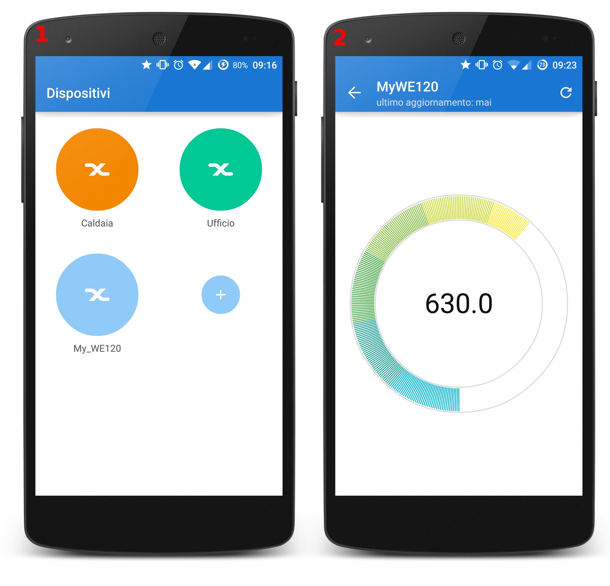
The most intuitive way to use and configure the WE120 is through the App, that can be downloaded for free from Android and iOS stores. The App offers a guided set-up procedure and a very user-friendly interface:

../_images/screenshot_app_1_2.png ../_images/screenshot_app_3_4.png
Image Description
1 All registered devices
2 Analog input visualization
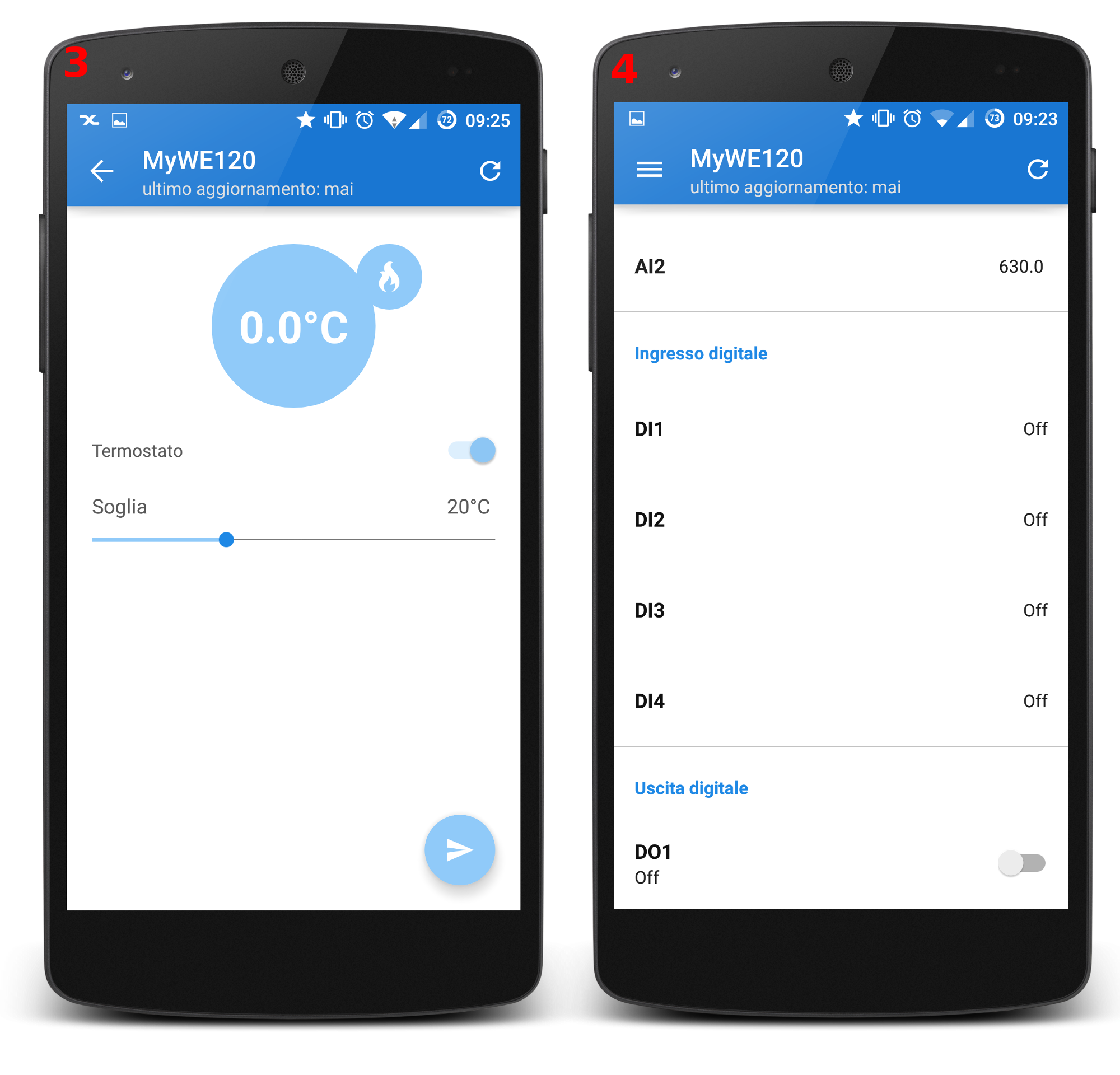
3 Thermostat mode
4 Display all the inputs and outputs
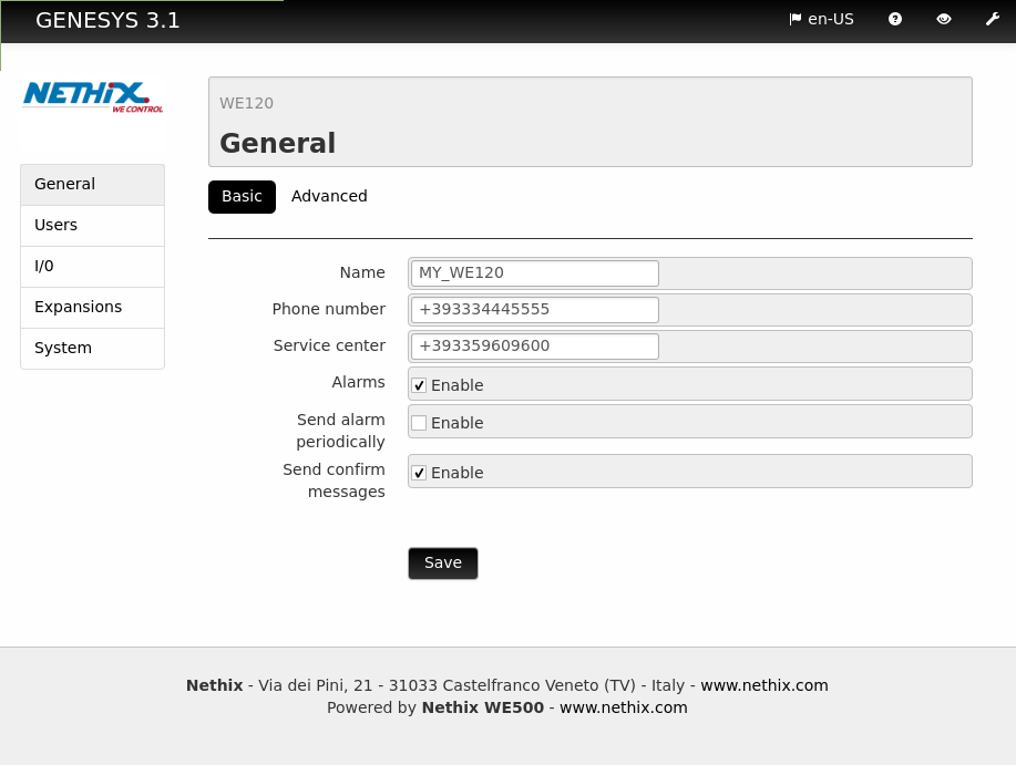
5.1.2. Genesys 3

The use of Genesys 3 grants a very easy set-up procedure for the device configuration. Genesys 3, available for free download form the following link, offers an intuitive and user-friendly interface and allows to configure all functions of the device and to upgrade the firmware in a very easy and fast way.

../_images/genesys_screenshot_1.png

5.1.3. Configuration through SMS

The configuration string has to be edited as a standard SMS message. Maximum message length is 160 characters, spaces included. Commands and parameters must be separated by spaces.

The following example shows a typical configuration session and use of the WE120 through SMS, that allows to check the correct operating of the system.

For a more comprehensive description of the available commands and relevant syntax see the section 6. Command description.

The following text on gray background has to be edited as SMS on any mobile phone and sent to the SIM number designated for the WE120.

Clear the device’s memory

DEFAULT 0000

Set the SMS Service Centre number (according to the designated Provider- the following example refers to Vodafone Italy)

CENTER 0000 +393492000200

Add new “administrator” user, authorized to receive unsolicited messages and alarms sent from the device

ADD 0000 +39493213213 Admin 3 1

The WE120 is now configured and ready for the use. Send the following commands from the administrator number to verify proper operation of the system.

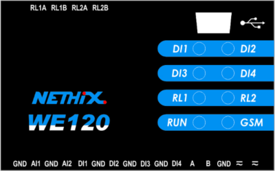
Send the following message to close relay n.1. See the status leds changing.

ON 1

Send the following message to open relay n.1. See the status leds changing

OFF 1

Read WE120 status. The device sends an SMS with all I/O status information.

STAT

Request the users list. The device replies sending an SMS including the requested information.

USERS

5.2. Configuration and use of the I/O expansions

The I/O module of the device can be expanded up to to:

  • 64 digital inputs
  • 64 relay outputs
  • 48 analogue inputs

using the I/O expansions, that can be optionally connected to the serial RS485 with Modbus

The available models, with relevant part-numbers, are the following:

Part number Type Description
90.11.001 6DI - 6DO Expansion with 6 digital inputs and 6 relay outputs
90.11.002 16 DI Expansion with 16 optoisolated digital inputs
90.11.012 4AI - 4T Expansion with 4 configurable analogue inputs

WE120 behaves as a master Modbus over RS485.

All the I/O expansions are modbus slaves with an address that can be configured through the dedicated button.

For all details regarding the connection, the configuration and the use of the I/O expansions, please refer to their respective user manuals.

To register a new I/O expansion to the WE120, use the command EXPADD. The new I/O will be added to the one of the WE120 and will be managed in the same way.

All additional inputs/outputs will be registered after the original ones. For example, the first analogue input of an 4AI expansion will be mapped on analogue input 3, since the first and the second ones are the standard analogue inputs of the WE120.

It’s not permitted to remove from the I/O one single expansion. To delete all the I/O expansions use the command EXPDEL, and the original factory configuration will be restored.

5.3. Device reset

If required, it’s possible to restore the factory settings of the WE120 following the procedure described below. All users, numbers, messages and configurations stored in the device memory will be permanently erased.

  • Switch off the WE120
  • Remove the SIM card and insert it into a mobile phone.
  • Delete all telephone numbers from the contacts list and add just one entry with the name DEFAULT
  • Insert the SIM card into the WE120 and switch on the system. The device will now execute all operations of the DEFAULT command and restore all factory settings.
  • After the reset of the device, take off the SIM card and insert it into a mobile phone.
  • Delete the command DEFAULT previously edited
  • Insert the SIM into the WE120 and switch on the system.

5.4. Firmware update

The Firmware update takes place through the Genesys 3 application. This procedure is described in the firmware update guide. Latest versions of firmware and Genesys are available at the Website doc.nethix.co.

6. Command description

The commands manual describes each one of the SMS commands that can be sent to the WE120 for configuration and normal operation. The commands manual is available at the Website https://nethix.co/en/we120/we120_commands_manual.html.


7. Safety guidelines

  • Nethix products support SIM cards from providers of all around the world, particularly from Europe Africa and Asia. However, there could be some incompatible SIM cards.
  • The device cannot receive/send SMS nor RING if the SIM card is not enabled to GSM services and network or credit is not available (if prepaid card is used).
  • Verify that the device is operated in an area covered by GSM network with sufficient signal strength for granting proper functioning.
  • In case of questions or doubts regarding the cost of the SMS service consult your Network Provider.
  • This device is only suitable for being installed by a qualified operator
  • Nethix is not responsible for improper use and/or its side effects
  • Nethix products are designed for typical use in industrial automation and/or home applications.

If you plan to use Nethix products in special applications where anomalies and discontinuity of service can have serious effect on human life or can cause physical or material damages, or where extremely high levels of reliability are required (for example in aerospace systems, in atomic energy control systems or n electro-medical devices), please contact Nethix for support to your particular application. Nethix is not responsible of damages caused from its products if such applications are not previously authorized.

not_recyclable The product shall not be treated as household waste. It shall be instead handed over to an appropriate collection point for the recycling of electrical and electronic products. For further information about recycling of this product, contact the local city office and/or the local waste disposal service.


8. Warranty and support

Nethix warrants to the buyer that the product will be defect-free within two years (24 months) from the date of purchase.

During warranty time, and against presentation of purchase invoice, the product will be repaired or replaced, at Nethix’s discretion, without any additional costs as regards spare parts and repair, if the damages are proven to be manufacturing defects.

Warranty will be voided if the product has not been used properly.

In case of technical problems the user can ask for support:


9. Return and repair

Product return to NETHIX must be previously authorized, requesting a RMA number.

Please send an Email at Nethix containing all following information:

  • Complete customer’s name and address
  • Distributor’s or Reseller’s name and address
  • Date of purchase
  • Product P/N and S/N as displayed on the product or the package
  • Detailed description of fault and/or reason for return

Nethix will communicate the RMA number, in order to start the return procedure of the product. The delivery of the goods shall be arranged DDP at Nethix premises. Products returned without factory seals will be automatically treated as out-of-warranty repair services.