Beside the main functions described on the preceding chapters, the WE300 allows to configure other parameters in order to meet all customers requirements.
10.1. Connectivity
Connectivity, i.e. i all communication channels to the device, is a very important part of the system’s setting.
From the page Administration → Networking it’s possible to access the screenshots, that allow to configure and start-up the different network interfaces and the different services.
- LAN
- SIM
- GPRS
- SMS
- Ring
- Email
10.1.1. LAN connection
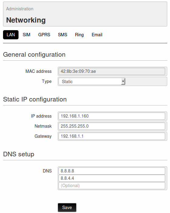
On the page Administration → Networking → LAN it’s possible to modify all parameters of the RJ45 Interface.
First of all the MAC address of the device will be displayed, with the option of using the LAN network on static IP address or on DHCP.
If the Static address will be selected, the following parameters must be set for the correct operation of the service:
- IP address static IP address assigned to the WE300. Make sure that the address is available and not used on other devices.
- Netmask Subnet mask. A valid netmask must be entered, according to the specifications of the own local LAN.
- Gateway Network gateway
- DNS DNS that can be assigned to the WE300 ( max. 3)
After settings modification the WE300 requires a reboot in order to activate them. If the entered parameters are correct, it’s possible to enter the web interface of the WE300 (even remotely if the network allows it), to send emails and send data to a Portal/Server.
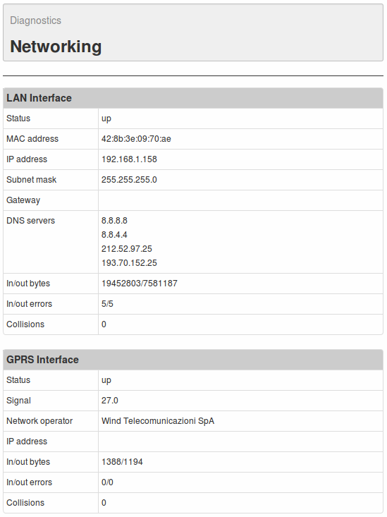
For further information regarding the status of the LAN connection, see page Diagnostics → Networking on section LAN Interface ( see 12. Diagnostic)
10.1.2. SIM parameters
Beside the parameters related to the connectivity, for the correct operating of the SMS and RING services, it could be necessary to define some SIM’s parameters according to the selected provider.
Those parameters are available on page Administration → Networking → SIM.
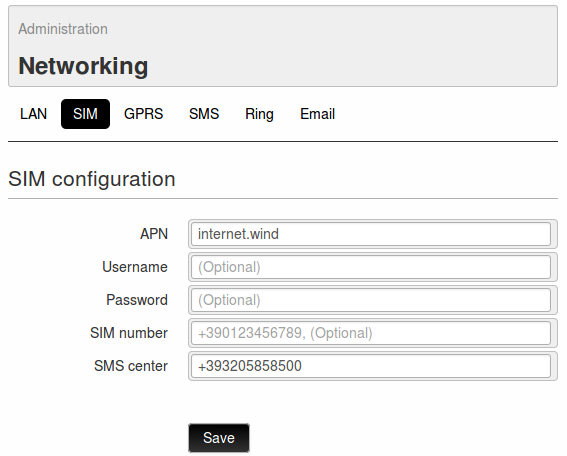
- APN: It’s the name of the access point of the GPRS/HSPA network. It changes according to the provider and to the contract with it (in some cases this may be not necessary). It’s an important parameter for a proper functioning of the connection. In case this should not be known, please contact the provider or Nethix Support.
- Username: it’s the username for the GPRS/HSPA connection. This field is normally blank, if it’s not differently required by the provider.
- Password: Password to be used for the GPRS/HSPA connection. This field is normally blank, if it’s not differently required by the provider.
- SIM number: It’s the Telephone number of the SIM inserted in the WE300. This is not relevant for the functioning (this number is never used by the WE300), but can be used for identifying the device later on.
- SMS center: It’s the SMS Service Centre of the Provider. With some types of SIM this could not be required. If this number is not known, please contact the Provider or Nethix Support.
10.1.3. GPRS connection
WE300 allows to establish a GPRS connection in order to enter the web interface of the device and send data or emails, even if no Ethernet connection is available.
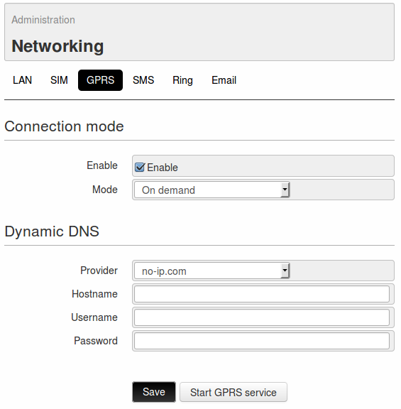
In order to activate the connection enter the page Administration → Networking → GPRS.
Once enabled the service with a flag on the field Enable, it’s required to specify whether the connection must be always on or on demand.
- On demand: the connection is activated on request by an authorized user through a wake-up message (11. Commands) and after 15 minutes is automatically disabled. If the activated services require a connection for data sending or email sending.., the connection of the WE300 will automatically be closed at the end of the configured operations.
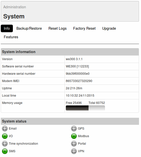
If the parameters have been properly configured, after a few minutes the GPRS connection will be activated. On the status panel, positioned on the right side of the web interface, the GPRS indicator will become green and beneath it the connection uptime and the relevant IP address will be displayed.
The WE300 offers also the possibility of associating the connection with a dynamic DNS service, choosing from the List of Providers available on section Dynamic DNS. This service allows to access the WE300 even if no static IP is available, since the device will be identified by the selected provider at every single connection, allowing the users to reach the web interface, just entering the hostname as configured on the browser. For further information see the Provider’s site or contact Nethix Support.
Make sure that the GPRS connection has been successfully established, by checking if all necessary operations have been executed:
- Provide the WE300 with an enabled data SIM card (rechargeable or with flat tariff contract)
- Enter the APN (10.1.2. SIM parameters) for the Providers, that require it.
- Connect the antenna and check the strength of the available GSM signal.
- Enable the GPRS service.
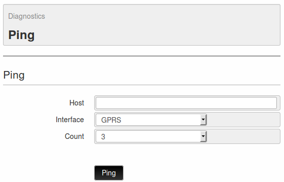
It’s possible to check the quality of the connection by using the diagnostic tool Ping (12.3. Ping).
Further information regarding the status of the connection can be found on page Administration → Diagnostics → Networking (12.2. Information of connectivity)
10.1.4. SMS
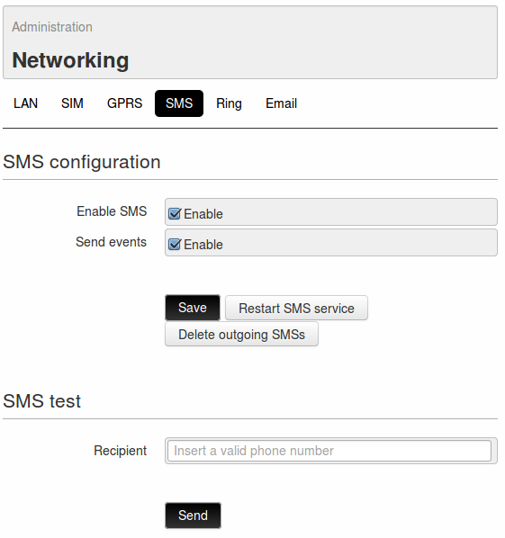
To enable/disable the SMS service go to page Administration → Networking → SMS.
Beside the flag for enabling the service, it’s possible to enable or disable the sending of pre-set SMS notifications (4. Events/Actions).
Enabling the service, it should be necessary to enter the SMS Service Centre number (10.1.2. SIM parameters).
Once enabled the SMS service, it’s possible to test the functioning through the section SMS test: entering a valid telephone number, complete with country code (for example +39NNNNNNNNNN for Italy), the WE300 will try to send an SMS with the following text ” Test message from WE300 “.
For granting the proper functioning of the SMS service, allowing the users to communicate with the WE300 and the WE300 to send alarm notifications, the procedure below must be carefully carried out:
- Enter the SMS Service Centre (10.1.2. SIM parameters).
- Enable the SMS service as described before
- Enable the SMS sending on event (field Send events on Administration → Networking → SMS)
- Define at least one user with activated SMS sending/receiving functions (9. Users)
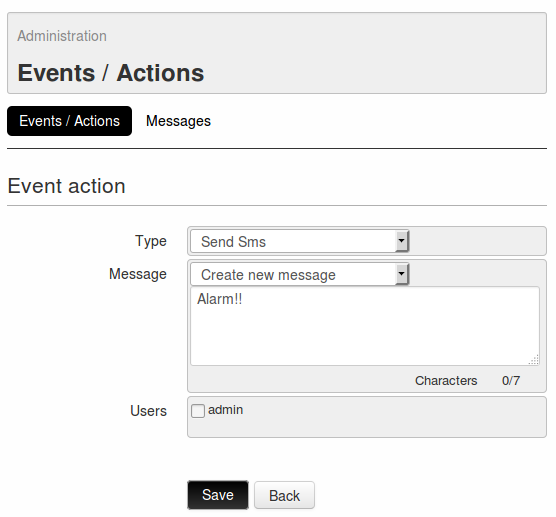
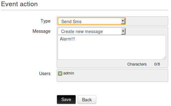
- Create one or more events as Send SMS action (se 4. Events/Actions).
- Make sure that the SIM is properly inserted and with enough credit.
- Make sure that the antenna is properly connected and that the available signal is strong enough.
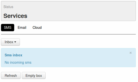
All sent and received SMS can be displayed on page Status → Services → SMS: the first page to be entered will show the SMS received by the device.
In the table the following information will be available:
- Number: shows the Phone number of the SMS sender
- Reception date: displays the date and time when the WE300 has received the message
- Text: contains the text of the received message
The button Refresh can be clicked at any time in order to update all information; Empty box for deleting all messages stored on Inbox.
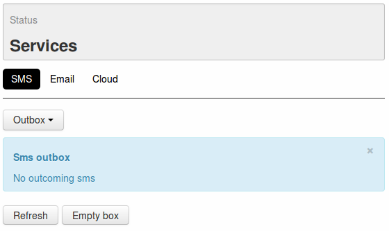
Clicking on the drop-down menu on the top of the table, it’s possible to pass from Inbox to Outbox.
On this table is possible to display all the messages not yet delivered by the WE300.
The available information are the following:
- Number: refers to the phone number of the message receiver
- Creation date: shows the date and time when the message has been created
- Text: displays the text of the message
The button Refresh can be clicked at any time in order to update all information; Empty box for deleting all messages available on Outbox (such messages won’t be delivered).
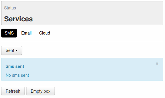
Clicking on the drop-down menu on the top of the table, it’s possible to pass from Outbox to Sent.
On this table are displayed some information regarding the SMS already delivered by the WE300:
- Number: shows the receiver of the delivered messages
- Send date: displays the date and time when the WE300 has delivered the message
- Text: contains the text of the sent messages
The button Refresh can be clicked at any time in order to update all information; Empty box for deleting all messages stored on Sent.
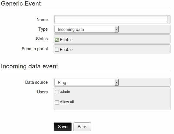
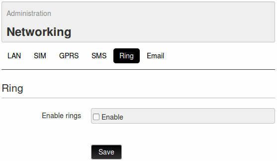
10.1.5. Ring
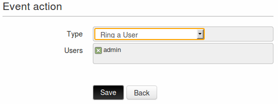
One of the actions that can be associated to an event (incoming or outgoing) is the RING, that can be sent or received to/by one or more registered users (4. Events/Actions).
To enable the Ring Function go to page Administration → Networking → Ring and enable the field Enable rings.
Once enabled the function and clicked on Save, it’s possible to use this option.
To make sure that this function is properly operating, it’s recommended to check the following points:
- Enable the Ring function, as described above.
- Define at least one user with valid telephone number, enabled to receive/send rings (see 9. Users)
- Make sure that the SIM card is properly inserted and voice call enabled.
- Make sure that the SIM card has enough credit to send rings.
- Make sure that the GSM antenna is properly assembled and that the signal is strong enough
10.1.6. Email
Before proceeding with the configuration of the WE300, it’s necessary to make the following:
- After the selection of the provider (Gmail, Yahoo, Hotmail etc..) enter the provider’s site and create a new valid mail account
- In the site of the provider, collect all information regarding the parameters to be entered in order to configure the mail service
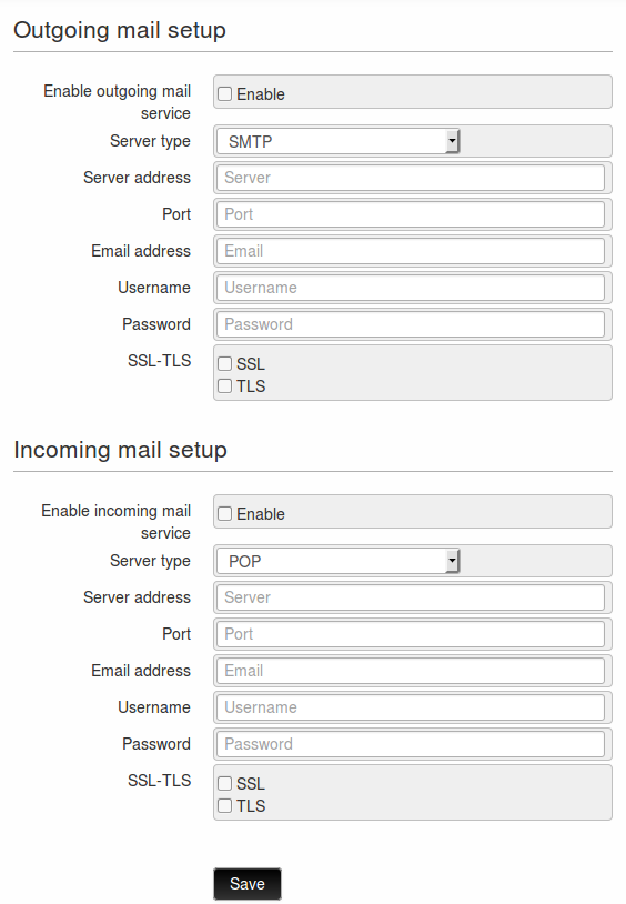
Once a new account has been created, it’s possible to proceed with the configuration of the WE300, enabling the outgoing emails, the incoming emails or both of them from the page Administration → Networking → Email.
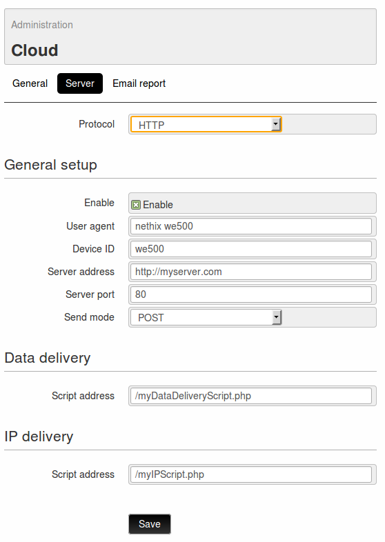
On the section Outgoing mail setup the parameters required for the email sending from the WE300 must be set:
- Enable outgoing mail service it enables/disables the email sending service.
- Server type it allows to choose the type of mail server (at the moment only SMTP available)
- Server address it’s the address of the mail server ( for example smtp.gmail.com)
- Port it’s the number of the access port (for example 587)
- Email address the email address associated to the WE300. This will be the address visualized by the receivers of the emails.
- Username It’s the username of the mail account associated to the WE300.
- Password It’s the password of the mail account associated to the WE300.
- SSL-TLS Encryption
Once clicked on the button Save, a new section, called Outgoing mail test, will appear on the bottom of the page: from this section it’s possible to send a test email to any address.
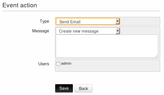
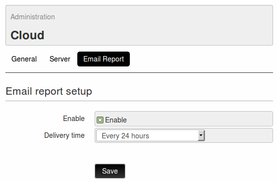
A properly configured mail service allows the WE300 to send notification mails to the configured users (see 4.2.1. Send Email)or to send scheduled reports (see 7.2.2. Email report).
On the section Incoming mail setup the parameters required for the email sending from the WE300 must be set:
- Enable incoming mail service: Enables/disables the email receiving service.
- Server Type: Type of mail server (at the moment only POP available)
- Server address: the address of the mail server (for example pop.gmail.com)
- Port: Number of the access port (for example 995)
- Email address: the email address associated to the WE300. The commands sent by the authorized users should be sent to this address.
- Username: It’s the username of the mail account associated to the WE300.
- Password: It’s he password of the mail account associated to the WE300.
- SSL-TLS: Encryption
A properly configured mail service allows the authorized users to send commands to the WE300 (see 6.2. Set/Get via SMS/Email commands and 11. Commands)
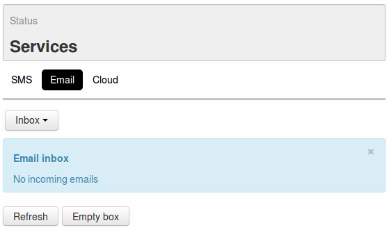
All sent and received emails can be visualized on the page Status → Services → Email.
The first page shows the emails received by the device:
On the displayed table the following information are available:
- Mail address: the mail address of the sender
- Reception date: Date and time when the WE300 received the email.
- Text: text of the received email.
At any time it’s possible to click on the button Refresh in order to update the information, or Empty box, in order to delete all messages available inside Inbox.
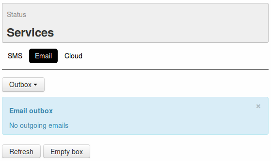
Clicking on the drop-down menu on top of the table, it’s possible to pass from Inbox to Outbox.
On this table it’s possible to visualize all the emails not yet delivered by the WE300. The following information will be shown:
- Mail address: in this filed is shown the address of the receiver of the mail.
- Creation date: It’s the date and time of the mail creation
- Attempts: it shows the sending attempts made by WE300
- Text: it displays the text of the mail
At any time it’s possible to click on the button Refresh in order to update the information, or Empty box, in order to delete all messages available inside Outbox ( deleted mails won’t be sent out)
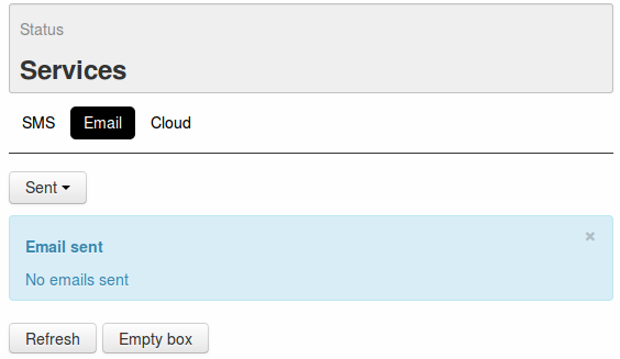
Clicking on the drop-down menu on top of the table, it’s possible to pass from Outbox to Sent.
On this table are displayed some information referred to the email already sent by the WE300:
- Mail address: in this filed is shown the address of the receiver of the mail.
- Creation date: It’s the date and time of the mail delivery
- Attempts: it shows the sending attempts made by WE300 before the successful delivery
- Text: it displays the text of the sent mail
At any time it’s possible to click on the button Refresh in order to update the information, or Empty box, in order to delete all messages available inside Sent.


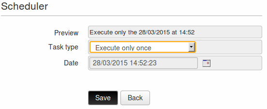
 located on the right side of the field Date, the calender will open and allow to select the hour, the day, the month and the year, when the action has to be executed.
Once the action has been executed, the event will be deleted.
located on the right side of the field Date, the calender will open and allow to select the hour, the day, the month and the year, when the action has to be executed.
Once the action has been executed, the event will be deleted.
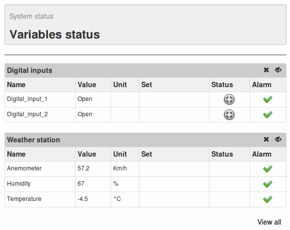
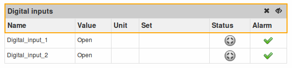
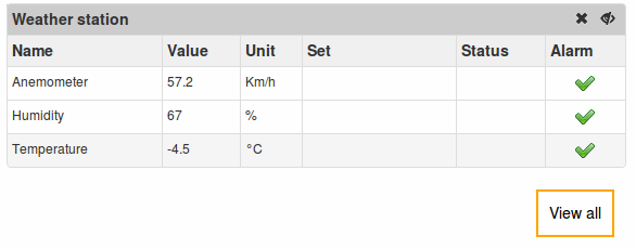
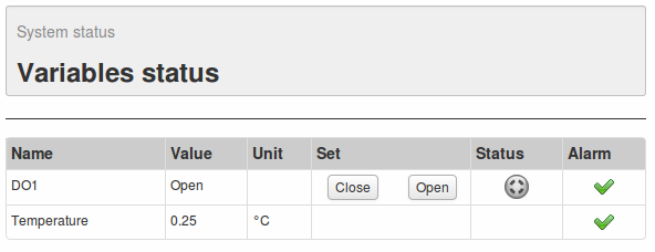
 or gray
  , according to the status and configuration of the variable.
 indicates that no active alarms are available. The icon
  indicates on the other hand the presence of an event configured as an alarm.

 The product shall not be treated as household waste. It shall be instead handed over to an appropriate collection point for the recycling of electrical and electronic products. For further information about recycling of this product, contact the local city office and/or the local waste disposal service.