Hardware manual

1. Overview
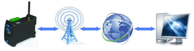
The WE300 is a remote monitoring, data logging and system control device based on GSM wireless networks that allows to continuously monitor unmanned processes and to remotely control devices and electronic systems.
The WE300 provides a built-in web server that allows the configuration, monitoring and system control of a given device through a LAN or GPRS connection.
The WE300 is a powerful wireless generic platform with the following characteristics:
2. Technical characteristics
| Characteristic |
Description |
|---|
| CPU |
CPU ARM9 AT91SAM9260 @ 210MHz |
| RAM |
64 MBytes |
| Flash |
1 GByte NAND |
| Operating System |
Linux 2.6 |
| Ethernet |
10/100 Mbit/s |
| Modem |
2G Quad band GSM/GPRS |
| Communication |
1 RS232 serial port
1 RS485 serial port
|
| Digital inputs |
4 inputs, non isolated, dry contact |
| Analog inputs |
2 inputs, non isolated, 0-5V, 0-10V, 0..20mA
(configurable for 4..20 mA), NTC 10K
|
| Digital outpus |
2 relays, 1A 30VDC |
| Power source |
9 - 32 VDC |
| Average absorption |
300 mA @ 12VDC |
| Peak absorption |
500 mA @ 12VDC |
| Weight |
220 gr |
| Dimensions (L x W x H) |
45 x 120 x 100 mm |
| Box |
Plastic, DIN bar mountable |
| Storage temperature |
-25° C - +85° C |
| Working temperature |
-10° C - +60° C |
| Humidity |
5% - 95% (non condensing) |
Warning
If the analog inputs are 0..20 mA, they can be used in the 4..20 mA by simply setting an offset when configuring the analog input.
3. Connections
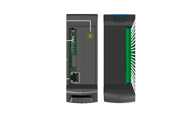

| Connector |
Description |
|---|
| 1 |
Bottom connector
Pluggable screw terminal, 20 poles, 3.81 mm step
|
| 2 |
RF SMA antenna connector |
| 3 |
SIM card slot |
| 4 |
Ethernet 10/100 MB/s RJ-45 connector |
| 5 |
Top panel button |
3.1. Bottom connector
| Connector |
Description |
|---|
| A |
RS485 signal A ( + ) |
| B |
RS485 signal B ( - ) |
| GND |
GND for RS485 |
| TX |
RS232 TX UART |
| RX |
RS232 RX UART |
| GND |
GND for UART |
| DI1 |
Digital input 1 |
| DI2 |
Digital input 2 |
| DI3 |
Digital input 3 |
| DI4 |
Digital input 4 |
| GND |
Digital inputs ground |
| AN1 |
Analog input 1 |
| AN2 |
Analog input 2 |
| GND |
Analog inputs ground |
| RL1A |
Relay 1 |
| RL1B |
Relay 1 |
| RL2A |
Relay 2 |
| RL2B |
Relay 2 |
| +VIN |
Power source input +VDC |
| GND |
Power source ground |
Warning
The pluggable screw terminals are listed from the front to the back of the device.
3.1.1. Connector electrical characteristics
Power source
Polarized VDC input, with internal protection diode compatible with the following tension rate:
Vnom = 12VDC [9.6V – 32V]
Analog input
Factory configured non isolated Analog Inputs
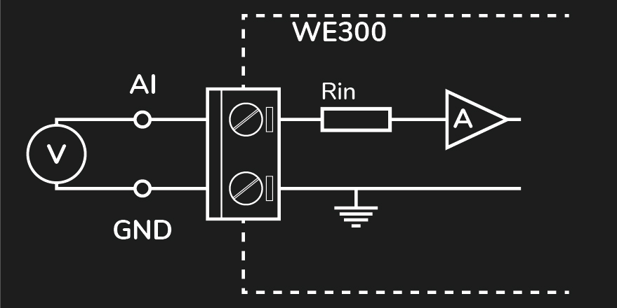
Admissible input range:
0 – 5 V
0 – 10 V
0..20 mA (4..20 mA configurable via software)
NTC 10K
Error
The analog inputs are not galvanic isolated. If necessary, for avoiding interference, analogical isolators can be placed externally.
Digital input
Dry contact, non isolated, low tension Digital Input
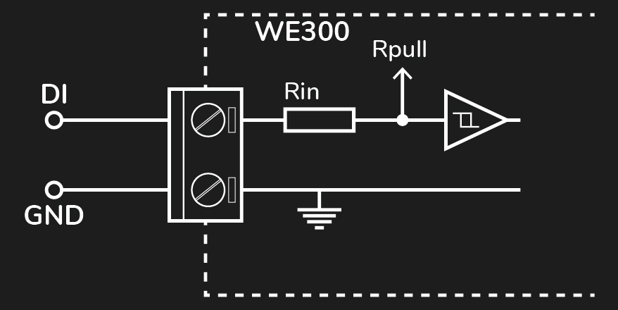
Error
The digital inputs are not galvanic isolated, they have an internal pull-up and are activated by closing the circuit with GND through a dry contact.
Relays
Relay load: 1A at 30VDC
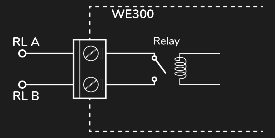
Error
Avoid to connect them directly to 230VAC network.
Serial ports
There are two serial ports:
- Standard RS 232
- Standard RS 485
3.2. Front panel

| LED |
Description |
|---|
| GPRS |
GPRS connection
Turned on when the GPRS data connection is active
|
| POWER |
Power source. It’s always turned on |
4. Installation
This chapter describes the installation procedure and first device start up.
In order to have a normal operating device, it is necessary to have a SIM card that allows to establish a GPRS data connections. Please check the carrier’s data planning for prices and costs of the service.
Verify that the device is installed in a physical position in which it receives sufficient 2G network coverage.
Note
The device has been tested and verified with SIM cards of the major European carriers such as Vodafone (Italy), T-Mobile (Germany) and O2 (Ireland). It has also been used with SIM cards of carriers in different parts of the world such as Africa and Asia. However, there is no warranty that it will work with all the existent SIM cards in the market. Please contact Nethix for further information.
4.1. SIM card and connections
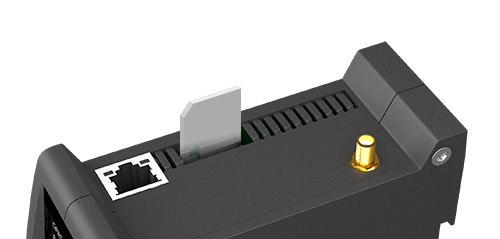
- Insert the SIM card in the WE300 as the image shows. The SIM card contacts must face the pluggable screw terminal and the cut angle faced to the front of the device.
Warning
Avoid to insert the SIM card when the device is turned on. After turning off the device and removing the power source, the SIM card can be inserted/removed.
- Mount the WE300 in a DIN bar allowing access to the SIM card and the pluggable screw terminals.
- Prepare the input and output connections to the pluggable screw terminals as required by the application.
- If required, connect the modbus cables using the signals TX, RX and GND or A, B, GND for the RS232 or RS485, respectively.
- Connect a quad band GSM antenna with the right cable and, if required, the extension being sure to have a satisfactory GSM signal. Check the network coverage with any mobile phone.
- Connect to the pluggable screw terminals the +VIN and GND of the bottom connector to an adequate power source.
4.3. System start-up
- The POWER LED will turn on when the WE300 is connected to the power source.
- After ~40 seconds all the application and services will be active. The monitoring, control and logging applications will be running and the web interface will be reachable.
- After ~30 seconds of step 2, the GPRS service will become active and the GPRS LED will turn on. The services that depend on this connection such as data delivery to a portal and email will be active.
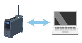
The initial WE300 configuration must take place locally in one of the two following modes:
- Point-to-point connection between the PC and the WE300 using a normal or cross Ethernet RJ-45 cable:
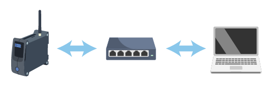
- LAN wired connection through a switch or hub:
The default network configuration of the WE300 is the following:
| Parameter |
Value |
|---|
| IP address |
192.168.1.160 |
| Netmask |
255.255.255.0 |
| Gateway |
192.168.1.1 |
| DNS |
8.8.8.8 |
4.4. Logging in the web interface
In order to establish a connection enter the IP address of the device in the browser’s URL:
http://192.168.1.160
The default credentials are:
| Username |
Password |
|---|
| admin |
admin |
Hint
It’s strongly recommended to change the default password after the first login.
It’s necessary that the PC belongs to the same subnet of the device. In this case the private network 192.168.1.X.
For connecting to the WE300 a standard Internet browser is needed. No drivers or specific software are required.
The recommended browsers that were also used for validating the web-interface are Firefox and Chrome. However, other browsers are known to work properly.
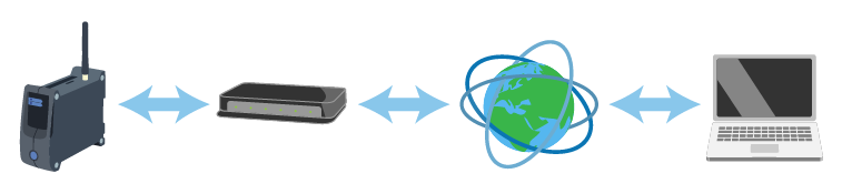
Successive access to the web interface can take place through different channels assuming that the device is properly configured:
5. Power off and reboot
Powering off the WE300 can be done in two ways:
- Using the proper icon at the right top of web interface. Only an administrator can power off or reboot the device.
- Using the Stand-by mode described later.
Error
Powering off the device by removing unexpectedly the power source could cause data loss or corruption.
6. Stand-by mode
The Stand-by functionality turns off all the system applications, such as the web server and the variables monitoring, setting the system to a low power consumption state.
Warning
This functionality must be always used before removing the power source from the device. Not doing so, could cause data loss or corruption.
6.1. Entering the Stand-by mode
For entering the Stand-by mode, press the top panel button and leave it pressed for approximately three seconds. During this time, the power LED will blink fast, then all the LEDs will blink together indicating that the system will enter the Stand-by mode
When the LEDs start blinking together fast, release the button immediately.
The power LED will turn-on again for several seconds and start blinking again slowly, approximately once every two seconds, indicating that the system has entered the Stand-by mode and that is in a low power consumption state.
The whole procedure takes approximately fifteen seconds.
Warning
Notice that leaving the top panel button pressed after all LEDs blink three times starts the network recovery procedure.
6.2. Leaving the Stand-by mode
When in Stand-by mode, the power LED blinks slowly, approximately once every two seconds.
Press the top panel button and leave it pressed. The power LED will start blinking fast for approximately three seconds, then it will remain turned-on. At this point the button can be released and the system will start-up normally.
7. Network recovery
For executing a Network Recovery, press the top panel button and leave it pressed for approximately six seconds. During this time the following actions will be executed twice:
- The power LED will blink fast for approximately 3 seconds
- Then, all the LEDs will blink together three times
After these six seconds, the power LED will turn-on and start blinking again slowly, approximately once every two seconds, indicating that the network recovery has been executed and the system is in Stand-by mode.
Execute the procedure for leaving the Stand-by mode for booting the device normally.
This is the default network configuration after the Network Recovery:
| Parameter |
Value |
|---|
| IP address |
192.168.1.160 |
| Netmask |
255.255.255.0 |
| Gateway |
192.168.1.1 |
Warning
Notice that the Network Recovery procedure is applied only to the Ethernet interface and not to the GPRS interfaces.
8. Safety guidelines
- Nethix products support SIM cards from providers of all around the world, particularly from Europe Africa and Asia. However, there could be some incompatible SIM cards.
- The device cannot receive/send SMS if the SIM card is not enabled to GSM services and network or credit is not available (if prepaid card is used).
- Verify that the device is operated in an area covered by GSM network with sufficient signal strength for granting proper functioning.
- In case of questions or doubts regarding the cost of the SMS service consult your Network Provider.
- This device is only suitable for being installed by a qualified operator
- Nethix is not responsible for improper use and/or its side effects
- Nethix products are designed for typical use in industrial automation and/or home applications.
If you plan to use Nethix products in special applications where anomalies and discontinuity of service can have serious effect on human life or can cause physical or material damages, or where extremely high levels of reliability are required (for example in aerospace systems, in atomic energy control systems or n electro-medical devices), please contact Nethix for support to your particular application. Nethix is not responsible of damages caused from its products if such applications are not previously authorized.
 The product shall not be treated as household waste. It shall be instead handed over to an appropriate collection point for the recycling of electrical and electronic products. For further information about recycling of this product, contact the local city office and/or the local waste disposal service.
9. Warranty and support
Nethix warrants to the buyer that the product will be defect-free within two years (24 months) from the date of purchase.
During warranty time, and against presentation of purchase invoice, the product will be repaired or replaced, at Nethix’s discretion, without any additional costs as regards spare parts and repair, if the damages are proven to be manufacturing defects.
Warranty will be voided if the product has not been used properly.
In case of technical problems the user can ask for support:
10. Return and repair
Product return to NETHIX must be previously authorized, requesting a RMA number.
Please send an Email at Nethix containing all following information:
- Complete customer’s name and address
- Distributor’s or Reseller’s name and address
- Date of purchase
- Product P/N and S/N as displayed on the product or the package
- Detailed description of fault and/or reason for return
Nethix will communicate the RMA number, in order to start the return procedure of the product.
The delivery of the goods shall be arranged DDP at Nethix premises.
Products returned without factory seals will be automatically treated as out-of-warranty repair services.