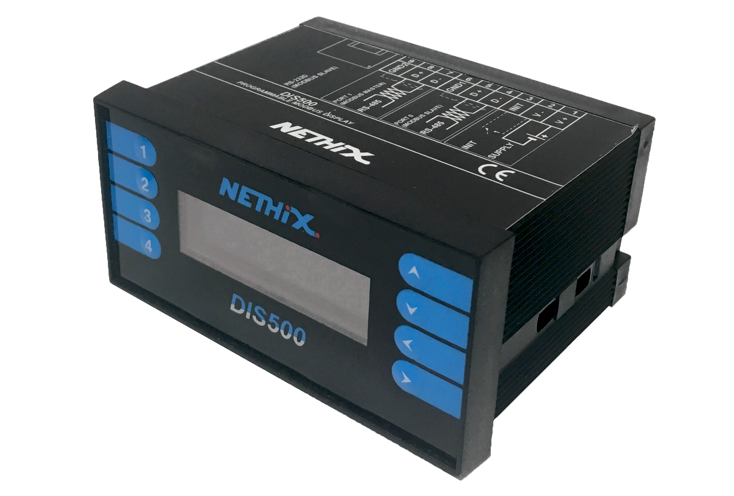
2. Device Connection
To start configuring DIS500, first power on the device and launch the newly downloaded software.
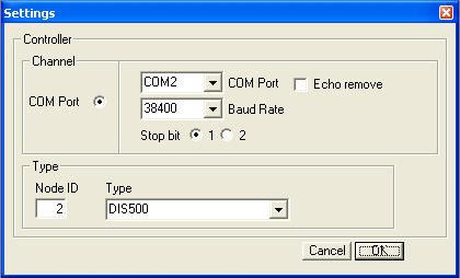
Then select Settings from the menu to specify the communication parameters with the device:
- COM Port Serial port to which the PC has associated the USB-RS485 converter
- Baud Rate Communication speed between the device and the PC
- Stop bit Number of stop bits. Select 1
- Node ID Modbus address associated with the DIS500 device in use
- Type Model of the device to interface with. Select DIS500
The Baud Rate and Node ID parameters, if not known, can also be viewed through the function buttons on the display.
To view the parameters, after powering the device, do the following:
- Hold the
 button and press the
  button
- Press

- Press
 to return to the previous view
Among the displayed parameters, Baud485 indicates the communication speed to be specified in the Baud Rate field, while Address indicates the value to be specified in the Node ID field.
After entering the required parameters, click OK.
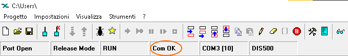
If the entered parameters are correct, the status bar should appear as shown in the following image:
3. Register Management
DIS500 has two RS485 serial ports, allowing it to interface with other devices using the Modbus protocol.
The Port 0 serial port, corresponding to terminals 4-5-6, is used to interface the device with the PC and to allow a Modbus client to send read/write commands to DIS500.
The Port 1 serial port, corresponding to terminals 7-8-9, allows the device to send read/write commands to one or more Modbus servers.
The display of DIS500 allows viewing the status/value of its internal Modbus registers, regardless of the port in use:
- When used as a server, it makes its unused internal registers available for a client to modify/read their value
- When used as a client, it reads data from one or more servers and assigns them to its unused internal registers
In the management of registers by the DIS Configurator software, no distinction is made between registers accessed through the Port 0 serial port and those accessed through the Port 1 serial port.
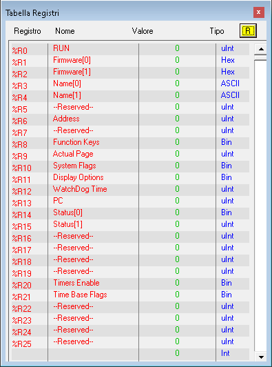
The list of internal registers already in use can be viewed by selecting View → Registers from the menu.
The registers in the range 0-25 are reserved and used by the device for internal purposes.
All others are available and can be used by the user.
To view the current value of the registers, you can click the  icon at the top right.
The system registers whose values are important to know are the following:
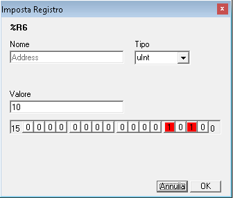
- %R6 Address
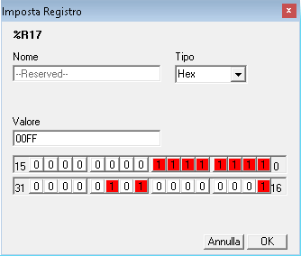
- %R17 Gateway Mask
3.1 Address (%R6)
Represents the Modbus address associated with DIS500, which a client must query to communicate with the device.
Corresponds to the Address entry viewable on the display through the function buttons and is associated with Modbus communication on the Port 0 serial port.
To modify it, simply double-click the corresponding row.
By selecting uInt from the Type field, you can enter a value (in the decimal system) and click OK to confirm.
Note that this parameter is also used by
DIS Configurator to interface with the device (see
2. Device Connection), so after changing it, the software may disconnect and ask for a new address.
Note
It is crucial that the address assigned to DIS500 is different from the addresses that it will query through the Port 1 serial port.
3.2 Gateway Mask (%R17)
Represents the range of Modbus addresses (not to be confused with registers) that DIS500 can query through the Port 1 serial port.
To ensure compatibility with the entire range provided by the Modbus protocol, set the register to 255 (or 00FF if displayed in hexadecimal).
If both serial ports are used (i.e., if DIS500 needs to function as both client and server simultaneously), it may be necessary to limit the access range (e.g., if you notice slowdowns when switching between display pages).
To modify it, simply double-click the corresponding row.
By selecting Hex (which stands for “hexadecimal”) from the Type field, the Value in the same field will be converted.
If the uInt value (represented in the decimal system) is 255, once Hex is selected, it will be displayed as 00FF.
The “high” part, or the two leftmost digits (in this example, 00), corresponds to the starting address of the range that DIS500 can access.
The “low” part, or the two rightmost digits (FF in the example), corresponds to the end of the range.
Assuming you want to limit the range DIS500 can access to Modbus addresses 1-2-3, the Value to enter will be 0103 (Hex).
Note
It is strongly recommended to specify a range that does not include the address assigned to DIS500 (see 3.1 Address (%R6))
4. Programming
At this point, you can start configuring a program to be loaded into the DIS500 device to define its operation.
This chapter explains how to program DIS500 to communicate with one or more Modbus servers (and then display the read registers).
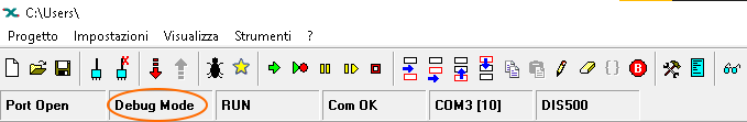
Once the device is connected to the PC via the DIS Configurator software, ensure that Debug Mode is set.
If not, click the  icon.
icon.
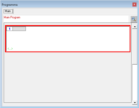
Then select View → Program from the menu.
As this is a new project, a completely empty program will be displayed:
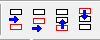
To insert new blocks into the program, use the Insert Before, Insert After, Move Up, and Move Down buttons.
For example, clicking Insert Before or Insert After will add a new block to the program.
Double-clicking on it will display all the functions that can be associated with the new block.
4.1 Register Block
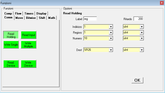
To define a series of Modbus registers that DIS500 should read from one or more servers (to then display them), first select the Comm tab from the Functions section.
The Modbus commands supported by DIS500 are listed:
- Read Holding
- Read Input
- Write Single
- Write Multiple
By selecting one, all the essential parameters for communication with the server will be displayed in the Options section.
- Label Name to associate with the block being defined. For the first block (which will appear at the top of the program), a label must be defined
- Delay Delay in ms between the execution of one block and the next. A delay of at least 100 ms is recommended
- Address Modbus address of the server to query. It must be different from the one assigned to DIS500 (3.1 Address (%R6)) and within the accessible range (3.2 Gateway Mask (%R17))
- Register Modbus register to start using the specified command from the Functions section
- Number Number of registers to apply the same command to (if the specified command type allows this usage)
- Dest Starting internal register where DIS500 will begin the association (default %R26, do not specify registers within the range %R0 - %R25 as they are reserved)
Example:
- Address: 10
- Register: 1
- Number: 5
- Dest: 30
DIS500 will apply the specified command from the Functions section to the Modbus server with address 10.
For this device, 5 registers will be queried, starting from register 1.
The value read from register 1 will be assigned to internal register 30, the value read from register 2 will be assigned to internal register 31, and so on.
Once all the parameters are set, press OK to confirm.
Multiple blocks of this type can be defined, even specifying a different Address each time, to query multiple Modbus servers.
When doing so, pay attention to the Dest parameter, ensuring that you do not include internal addresses already used in previous blocks.
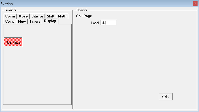
4.2 Display Block
The next step is to add a new block that initializes the display of the read parameters.
The elements to be displayed and their arrangement will be defined later; however, initializing the display is necessary to inform DIS500 of this intention.
To do this, simply click the Insert After button and double-click on the area of the newly added block.
From the Functions section, select Display.
Click the Call Page button on the left and confirm by clicking OK from the Options section after assigning a name to the block in the Label field.
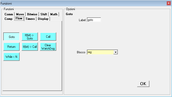
4.3 GoTo Block
The last block to define ensures the program runs correctly, making all previous blocks execute cyclically.
Click the Insert After button and double-click on the area of the newly added block.
From the Functions section, select Flow.
Click the Goto button in the Functions section.
In the Options section, the Label field can be omitted. However, you must select the name of the first defined block in the Block field.
It is crucial that the GoTo block points to one of the previously created blocks (the first one).
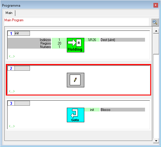
If you intend to acquire registers from a server device (thus from serial Port 1), the GoTo block should point to the first Registers block, as shown in the following image:
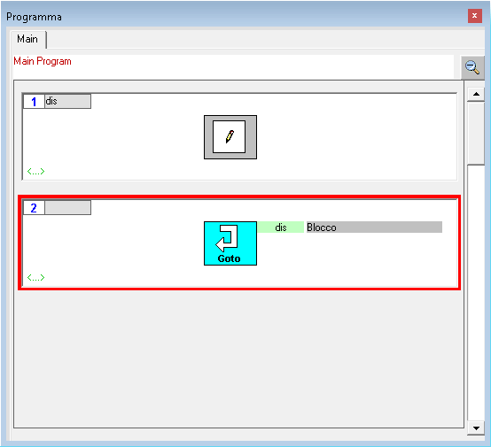
If you intend to use DIS500 as a server device (thus from serial Port 0), the Registers block should not be defined. The GoTo block should point to the Display block, as shown in the following image:
At this point, you can proceed with programming to decide which elements to display and where to place them.
5. Display Visualization
To organize the content of the pages displayed on the screen, first select Tools → Display from the menu.
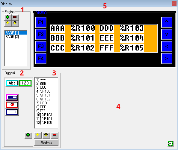
- 1 Section dedicated to Pages to be displayed on the screen. Click
 to add a new one,
  to delete a previously created one, and
  to move a page to another position.
- 2 Objects section where you can select which objects to display on the screen. The
 allows you to insert a string, while the
  allows you to display the value of an internal register. After selecting the element to be represented, click to add it to the list of created objects.
- 3 Section dedicated to managing previously created Objects. By selecting one, it can be deleted by clicking the or modified from the area on the right.
- 4 Section where all parameters useful for configuring a selected object will be displayed. At the bottom left, there is the
 button, which when pressed, will show the changes made in the preview area.
- 5 Area where a preview of the elements to be displayed on the screen will be shown after selecting the page to preview.
The objects explained in this manual are:
- Abc String to be displayed next to a value, to specify which read parameter it refers to.
- 123 Allows you to specify the value of which internal register to display, regardless of whether it is a value obtained from serial Port 0 or serial Port 1.
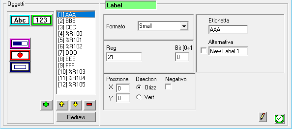
5.1 Abc Object
After adding one from the Objects section, the following fields will be displayed in the configuration area of the selected object:
- Format Allows you to choose the size the object should take on the display. Available options are Small, Medium, and Large.
- Reg Internal register to which the string will be associated. Leave the default value 21 for all created strings.
- Bit Leave the default value 0.
- Position X Allows you to enter a numerical value to decide the position where the object should be represented relative to the X-axis.
- Position Y Allows you to enter a numerical value to decide the position where the object should be represented relative to the Y-axis.
- Direction Allows you to specify whether the object should be displayed horizontally or vertically.
- Negative Leave disabled.
- Label Allows you to specify the string to be displayed on the screen.
- Alternative Leave disabled; the content of the field is irrelevant.
After making any changes, you can click the button to see them represented in the preview area.
5.2 123 Object
After adding one from the Objects section, the following fields will be displayed in the configuration area of the selected object:
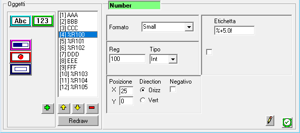
- Format Allows you to choose the size the object should take on the display. Available options are Small, Medium, and Large.
- Reg Internal register whose value will be displayed. It can refer to an internal register acquired through serial Port 0 or one acquired through serial Port 1.
- Type Allows you to define the format of the data to be represented. Options include uInt (16-bit unsigned integer), Int (16-bit integer), uLong (32-bit unsigned integer), Long (32-bit integer), and Float (32-bit floating point).
- Position X Allows you to enter a numerical value to decide the position where the object should be represented relative to the X-axis.
- Position Y Allows you to enter a numerical value to decide the position where the object should be represented relative to the Y-axis.
- Direction Allows you to specify whether the object should be displayed horizontally or vertically.
- Negative Leave disabled.
- Label Format in which the register value will be displayed. Leave %+5.0f as the default setting.
Once all changes are made, click the  button to confirm.
6. Upload Configuration
At this point, the configuration can be uploaded to the DIS500 device.
To do this, click the  icon located on the toolbar.
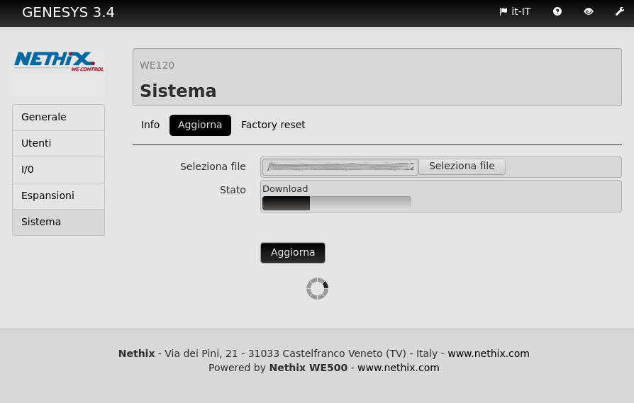
The download screen will be displayed (understood as downloading the configuration from the PC to the DIS500 device).
Then click the Download button to start the process and wait for the progress bar below to complete.
Before using DIS500 with the newly created configuration, ensure to exit the debug mode and put the device in Release Mode by clicking the  icon.
icon.
After completing the operations, remember to save the newly created project before closing the DIS Configurator software: the configuration uploaded to a DIS500 cannot be downloaded from the device itself.
It is therefore recommended to create a copy of the project on your PC for each configured DIS500.