Configuration Wizard
1. Overview
The simplest and safest way to configure TP100 is to use the online configurator provided by Nethix, which can be found at the following link:
Configuration Wizard
The configurator allows to define which Modbus registers TP100 should read/write and the Modbus function to be used for accessing, setting characteristics such as the name and measurement unit to display, scaling parameters for the read value, setting an access password for registers, and much more.
Thanks to the preview available on the right side of the configurator, you can see the real-time arrangement of registers on the display and modify it with a simple drag & drop.
After completing the operations, you can download the configuration file (in JSON format) and load it into the device by simply connecting TP100 to your PC via USB-C cable.
Further information regarding the configuration upload operations can be found in the user manual (
User manual).
From the online configurator, you can also upload a previously generated JSON file. Once uploaded, the preview will immediately display it, allowing configuration modifications.
The following chapters will explain the features and characteristics of the online configurator.
The information contained in this document is subject to change without prior notice.
2. Description of Fields on the Page
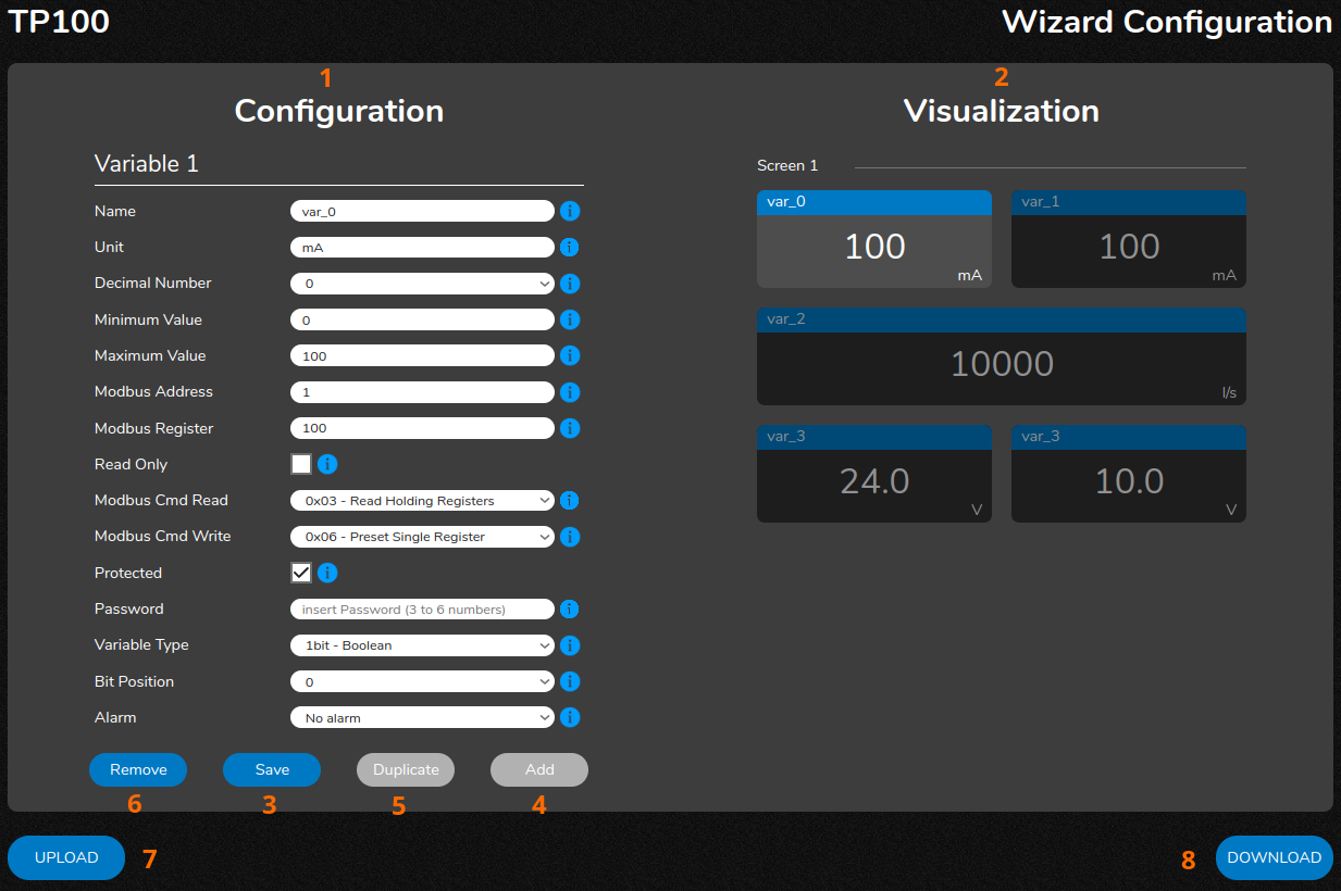
- Configuration: This area displays all configuration parameters related to the Modbus register to access. The description of each field can be found in the next chapter.
- Visualization: The right side of the screen displays a real-time preview of the tile arrangement associated with Modbus registers. The arrangement shown in the preview exactly matches the one shown on the display once the configuration is loaded.
- Save: This button saves the settings for the selected register.
- Add: This button adds a new Modbus register. By clicking it adds a tile in the first available space in the Visualization section. The position of the new tile can be modified with drag & drop.
- Duplicate: This allows duplicating the selected register, creating a new one (and consequently a new tile of the same size). This can be useful when creating multiple similar registers.
- Remove: This removes the selected register/tile. This action is irreversible.
- Upload: This allows selecting a configuration file from your PC. If the uploaded file contains a correct configuration, the preview will display it on the right side of the screen, allowing configuration modifications.
- Download: This allows to download the configuration file to be loaded onto TP100.
Next to each element in the Configuration section, you’ll also find the  icon.
Hovering over it with the mouse cursor, it displays information related to the associated field.
icon.
Hovering over it with the mouse cursor, it displays information related to the associated field.
3. Configuration - Configuration Parameters
Below are the descriptions of all the fields that allow to define the Modbus register to access, available in the Configuration section on the left side of the configurator.
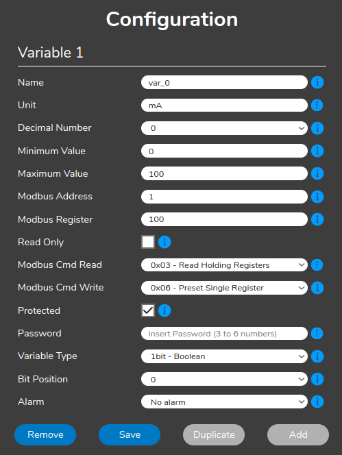
- Name: Name to be assigned to the register. It will be displayed at the top of the tile, up to 31 characters.
- Unit: Measurement unit associated with the quantity to be read. It will be displayed at the bottom right of the tile. Up to 9 characters are allowed.
- Decimal number: Number of decimal places to report in the read value. Up to 4 digits are allowed. Selecting 1bit - Boolean in the Variable Type field it will restrict selection to 0.
- Minimum Value: Together with Maximum Value, it scales the read value within the desired range. The minimum value depends on the selection made in the Variable Type field. See section 3.2. Variable Type for more information.
- Maximum Value: Together with Minimum Value, it scales the read value within the desired range. The maximum value depends on the selection made in the Variable Type field. See section 3.2. Variable Type for more information.
- Modbus Address: Modbus address of the device that TP100 will interface with, from 1 to 255 (per Modbus standard).
- Modbus Register: Modbus register to read from the device that TP100 will interface with. A number from 0 to 65535 can be specified.
- Read Only: When enabled, sets the tile to read-only mode, preventing the user from modifying the register value via the touch display.
- Modbus Cmd Read: Modbus function to be used to access the register specified in the Modbus Register field. It should be selected basing on the information in the manual of the device that TP100 will interface with. Supported Modbus functions are listed in section 3.1. Supported Modbus Functions.
- Modbus Cmd Write: Modbus function to be used to modify the value of the register specified in the Modbus Register field via touch display. This field is only available if Read Only is not enabled. Select based on the information in the manual of the device that TP100 will interface with. Supported Modbus functions are listed in section 3.1. Supported Modbus Functions.
- Protected: Enabling this option it allows to define a password for write access to the Modbus register in question.
- Password: Available only if Protected is enabled.It defines a numeric password (3 to 6 digits) that the user must enter on the display to modify the Modbus register value. A different password can be defined for each register.
- Variable Type: Selects the format of the variable associated with the Modbus register. Depending on the selection, the tile may assume different sizes. More information is available in the dedicated section (3.2. Variable Type).
- Bit Position: Available only for 1bit - Boolean and 8bit - Byte variables. Selects the bit to associate with the variable, where 0 represents the least significant bit of the word/register.
- Alarm Threshold: Defines the alarm threshold value. Depending on the condition specified in the Alarm field, when the register is in alarm, the top edge of the tile will be highlighted in red.
- Alarm: From this field, you can select one of the following alarm conditions:
- No alarm: If no alarm threshold configuration is desired.
- Equal to threshold: The register will be in alarm when the read value matches the set threshold.
- Less than threshold: The register will be in alarm when the read value is below the set threshold.
- More than threshold: The register will be in alarm when the read value is above the set threshold.
Note
TP100 follows Modbus addressing starting from 0. In the Modbus Register field, registers should be reported according to this convention, without offset (Example: Reg 40001 -> Reg 0 in TP100).
3.1. Supported Modbus Functions
TP100 supports the main register access functions provided by the Modbus protocol standard.
Modbus functions allow reading and writing data to and from the Modbus server device that TP100 will connect to.
It is important to choose the correct Modbus function based on the device manual intended to communicate with TP100.
In case TP100 is connected to a Nethix device (such as WE500+), ensure to define the same functions on both devices.
For further information regarding the connection of TP100 with WE500+, refer to the dedicated guide.
3.1.1. Read Functions
Supported read functions, that allow TP100 to obtain values from connected device registers, are as follows:
- 0x01 - Read Coil Status: Allows reading the status of a coil. The read value can be 0 or 1 (which usually corresponds to the ON/ OFF state of a digital output coil). If the Modbus server device allows it, functions 0x05 or 0x15 are used to modify the coil status.
- 0x02 - Read Input Status: Allows reading the status of a digital input. Again, the read value will be 0/1 (ON/ OFF). Typically, registers read with this function are Read Only and do not allow modification of their state by the Modbus Client device (which is TP100 in this case).
- 0x03 - Read Holding Registers: this function allows to read the overall value of the word/register (8-bit, 16-bit, or 32-bit, depending on the variable type). Functions 0x06 or 0x16 are usually used to access registers for writing, that are read with this function.
- 0x04 - Read Input Registers: This function theoretically allows accessing the overall value of the word/register. Usually, these registers are considered Read Only.
Note
To determine which read function to use, consult the technical manual of the device intended to connect to TP100.
3.1.2. Write Functions
Supported write functions that allow TP100 to modify values of connected device registers are as follows:
- 0x05 - Force Single Coil: This function can be used to modify the value (if allowed) of a register read with function 0x01.
- 0x15 - Force Multiple Coils: This function can be used to modify the value (if allowed) of a register read with function 0x01.
- 0x06 - Preset Single Register: This function is usually used to modify the value (if allowed) of a register read with function 0x03.
- 0x16 - Preset Multiple Registers: This function is usually used to modify the value (if allowed) of a register read with function 0x03.
Note
Commands 0x05 and 0x15 will only be available when 0x01 is selected as the read function. Conversely, commands 0x06 and 0x16 will not be available in this case.
This depends on the specifications of the Modbus protocol, which requires that the write function is consistent with the read function.
3.2. Variable Type
The Variable Type parameter allows to define the bit size of the variable associated with the Modbus register, specified in the Modbus Register field.
Based on the selection made (also in accordance with the specifications of the device to be connected to TP100), the size of the tile associated with the register may vary.
Tiles can be of two sizes:
- Half: Occupies half the display horizontally and one-third vertically.
- Full: Occupies the entire available space horizontally and also one-third vertically.
The variable types displayed on half tiles are:
- 1bit - Boolean: Value range: 0/1. If the Modbus server device allows it, multiple variables (up to 16) of this type can be created for each Modbus register using the Bit Position field. In this case, each variable must have a different bit position, where bit 0 is the least significant bit and bit 15 is the most significant.
- 8bit - Byte: Value range: 0/255. If the Modbus server device allows it, up to 2 variables of 8 bits each can be created for each Modbus register, where bit 0 represents the least significant byte and bit 8 represents the most significant byte.
- 16bit - Half signed: Value range: -32768/32767.
- 16bit - Half unsigned: Value range: 0/65535.
Variables represented by full tiles are:
- 32bit - Int signed: Value range: -2147483648/2147483647.
- 32bit - Int unsigned: Value range: 0/4294967295.
- 32bit - Int signed inv: Value range: -2147483648/2147483647.
- 32bit - Int unsigned inv: Value range: 0/4294967295.
- 32bit - Float: Value range: 0/4294967295.
- 32bit - Float inv: Value range: 0/4294967295.
Note that the ranges listed above refer to raw values read via Modbus and do not take into account any scaling defined by the user using the Minimum Value and Maximum Value fields.
EXAMPLE
- Variable: 16bit - unsigned
- Minimum Value: 0
- Maximum Value: 100
Although TP100 will actually read a value between 0 and 65535, on the display the variable can assume values between 0 and 100, scaled proportionally, where 0=0 and 100=65535.
32-bit inv variables differ from their standard counterparts (without the inv designation) due to the priority given to the register.
For variables without the inv designation, the most significant register has the highest value, while for inv variables it is the opposite.
Example:
- 32bit - Float variable defined on register 0. Register 0 is the least significant, and register 1 is the most significant.
- 32bit - Float inv variable defined on register 0. Register 0 is the most significant, and register 1 is the least significant.
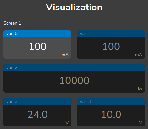
4. Visualization - Display Preview
The Visualization section displays a real-time preview of the tile arrangement based on the user’s configuration.
This preview shows the exact layout of elements that will appear on the TP100 display once the current configuration is loaded into the device.
Each newly added element is placed in the first available space, but users can rearrange elements as desired by selecting a tile and dragging it to any position or page on the display.
Each display page corresponds to three rows where elements can be arranged freely. When the current page’s space is full, a new page is automatically created.
Selecting a previously configured tile with the mouse in the Visualization section displays its parameters in the Configuration section, allowing modifications.
Tiles can be of two types:
The characteristics of each type are described in section 3.2. Variable Type.
Note that tiles can be freely rearranged to organize displayed elements according to user needs.
However, intentionally leaving blank spaces is not allowed.
5. Upload/Download - Downloading and Uploading Configuration
Once all Modbus registers that TP100 will access have been configured (see 3. Configuration - Configuration Parameters) and the layout of elements on the display has been decided (see 4. Visualization - Display Preview), you can download the configuration file to be loaded into the TP100 device.
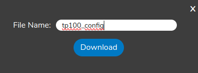
To do this, simply click the DOWNLOAD button located at the bottom right of the interface.
A pop-up window will appear where you can assign a name to the file that is about to be downloaded.
Clicking Download will save the file in the default directory of the browser being used.
The file generated by the online configurator is in JSON format and can be opened/modified using a compatible text editor.
It is strongly recommended, however, not to manually make changes but to use the online configurator for this purpose instead.
It is also possible to upload a previously created configuration file to make necessary changes.
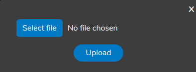
To do this, click the UPLOAD button located at the bottom left.
A pop-up window will appear where you can click Select file to choose the configuration file to upload.
The uploaded file will be analyzed by the page to verify that it is a properly formatted JSON file containing all expected parameters.
If the upload is successful, the preview of the newly uploaded configuration will be displayed, allowing further modifications.
For information on how to connect
TP100 to your PC to upload the configuration file generated by the online configurator, refer to the device user manual (
User manual).
Note that the name of the file uploaded via the Upload procedure is not relevant, but it must have the .json extension.