The events and actions allow to set the conditions for alarms or notifications, according to the value or status of a variable.
The event is the necessary condition to generate an action.
Actions allow to trigger automated logics, to communicate with other devices, to send SMS notifications, Emails, Chat and other.
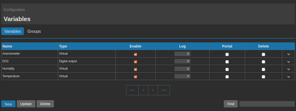
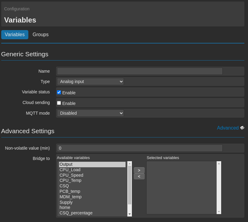
Before creating Events/Actions, it’s necessary to have variables.
4.1. Events
The events allow the WE151 to get aware, when a monitored parameter has crossed a certain threshold, set by the user.
There are different types of events, and for every type there are several parameters, that allow to have high flexibility in the monitoring and control of a system.
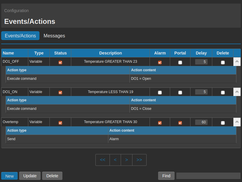
To create an event, it’s necessary to get to the page Configuration → Events/Actions → Events/Actions and then click on the tab New.
The tab Delete allows to delete one or more selected events, while with the tab Update it’s possible to make some modifications as for instance to able/disable one or more events, or to notify them as alarms and send them to a web portal.
In order to recall one or more events, it’s possible to use the field Find that allows to make a query based on name.
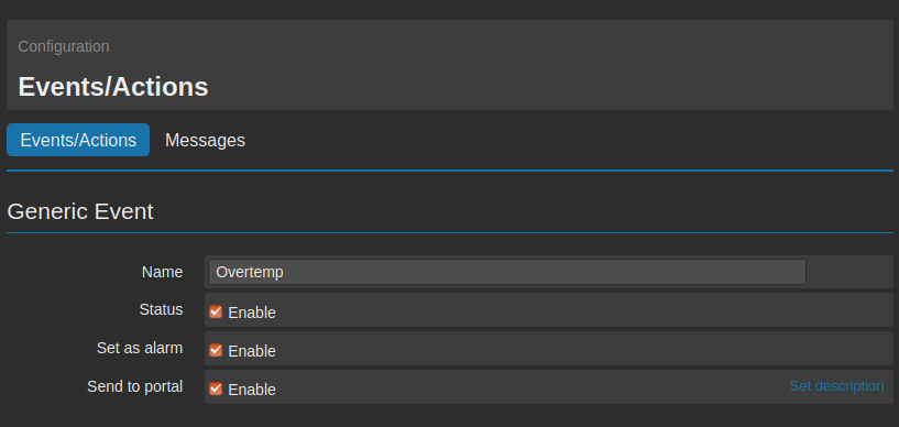
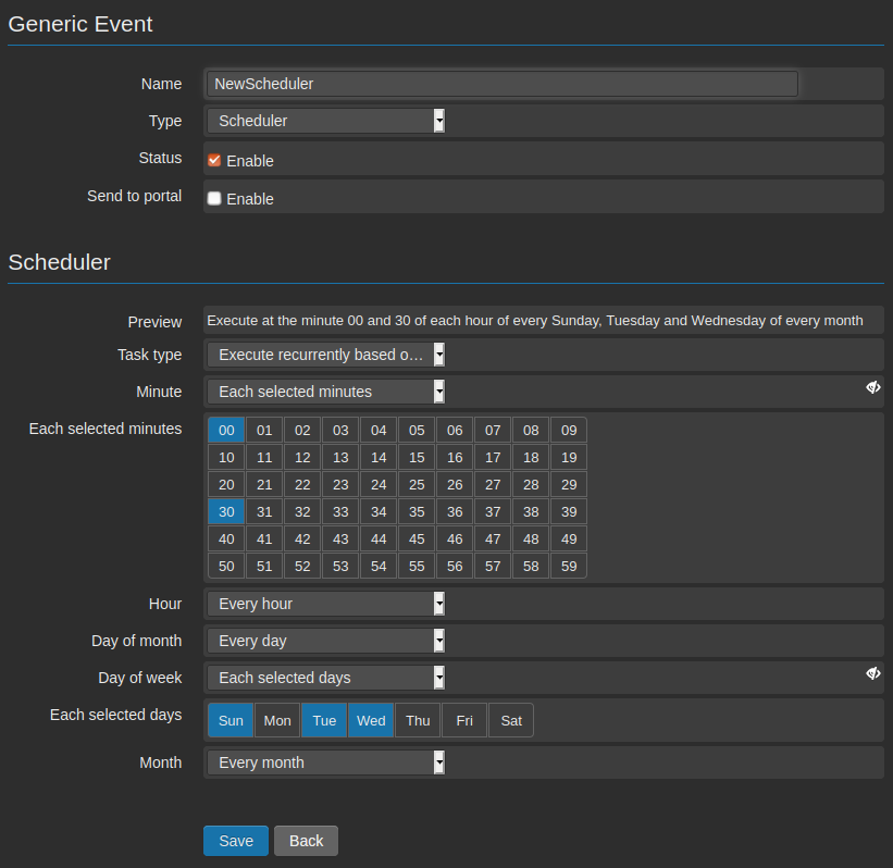
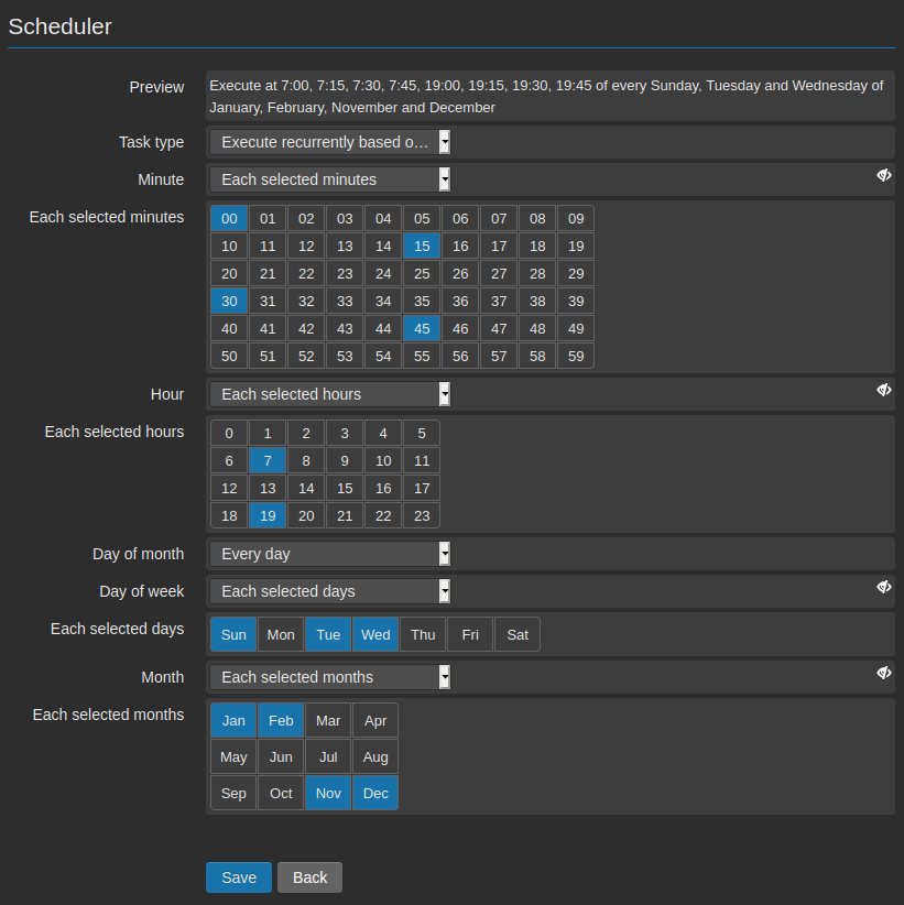
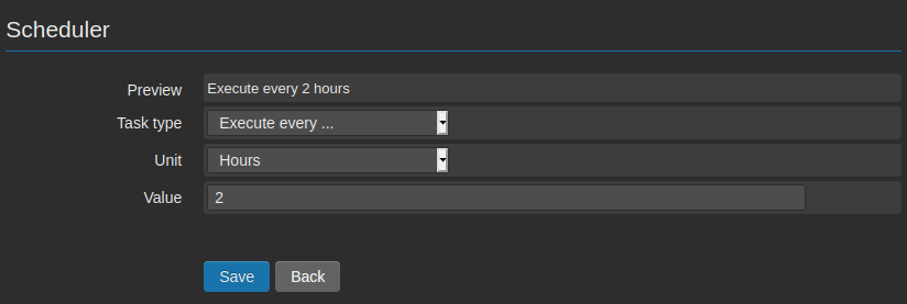
When an event is created, after assigning a name, it’s necessary to confirm the type of event among Variable, Incoming data or Scheduler (see 5. Scheduler).
There are a few generic options that can be enabled according to the selected event’s type: it’s possible to decide wether to enable the event from Status or not, wether to display it or not as an alarm from the field Set as alarm and wether to send it or not to a web portal from the field Send to portal.
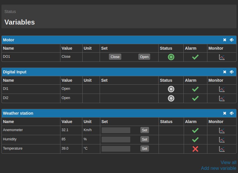
In case the option Set as alarm is enabled, at the occurrence of the event a red “X” will appear on the page Status → Variables, near the name of the variable (on the column Alarm); this allows to see at a glanace the presence of a critical condition.
The option Send to portal allows on the other hand to send an event to a web portal. At the occurrence of the event, the WE151 will execute the associated actions and send to portal a string, containing the name of the event and further relevant information.
4.1.1. Events on variables
It’s an event that occurs when a variable reaches a certain value or a certain status.
The behaviour of this type of event is determined by the behaviour of the variables, that will be associated to it.
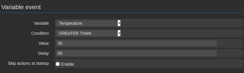
First of all it’s necessary to choose a variable from the field Variable.
From the drop down menu, it’s possible see all variables previously created and select the one, on which an event has to be configured.
The second parameter to be selected is the one connected to the Condition. The possible options are EQUAL, NOT EQUAL, GREATER THAN, GREATER OR EQUAL THAN, LESS THAN and LESS OR EQUAL THAN.
It’s necessary to set the value to be considered as threshold for triggering the event, on the selected variable, entering a numerical value on the field Value.
It’s possible to set a delay on the field Delay. The value is expressed in seconds and it avoids that the event is triggered immediately.
The variable Value must remain under the defined condition (Condition) for a time not shorter than the one configured in Delay, before the defined event is finally considered activated and the associated actions are executed.
It’s also possible to set that an event (and its associated actions) are ignored, if it’s found activated after a shut down/reboot of the system. This is possible enabling the option Skip action at startup.
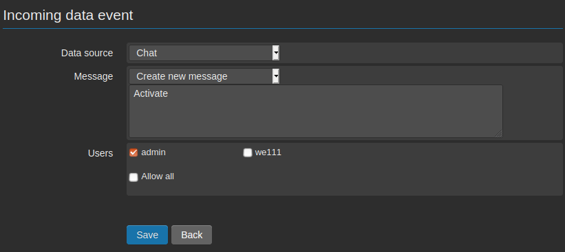
4.1.2. Incoming data
The incoming events are those triggered by inputs coming from external sources:
This function gives the possibility to create customized commands to be sent to the device. The commands could be sent by users or other devices.
After the selection of the desired option from the field Data source, it has to be entered the text of the command (to be entered on the field Message).
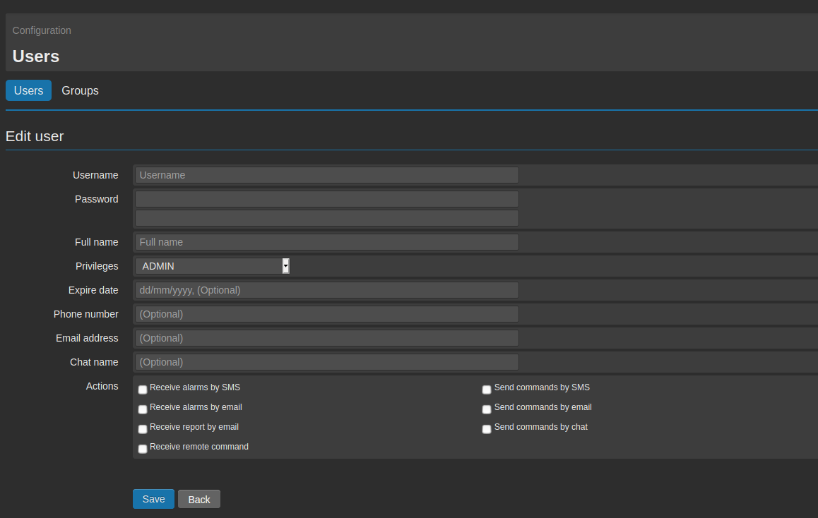
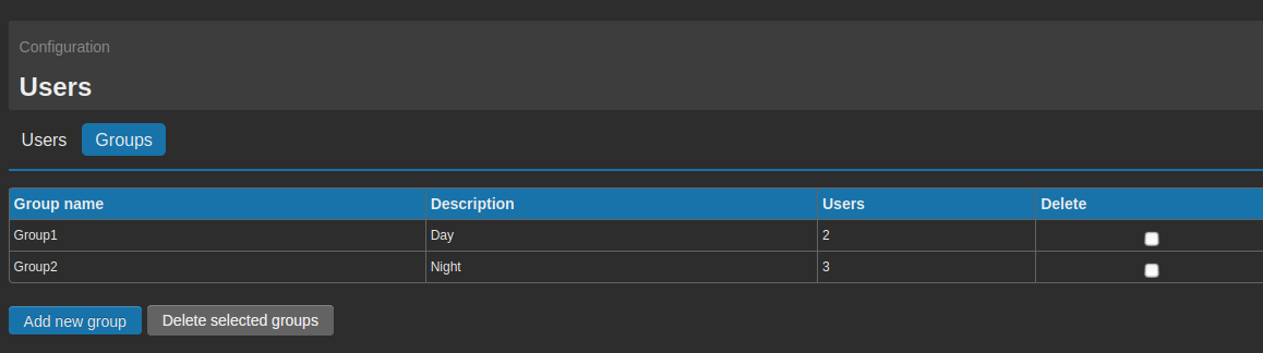
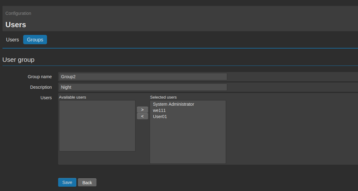
On the field Users can be eventually selected the users or the groups of users enabled to send the command.
The actions associated to such an event will be then executed at the receipt of the text, as entered on the field Message, on condition that it’s sent by one of the selected users.
Note
The commands must be written case sensitive, as originally entered in the configuration.
Note
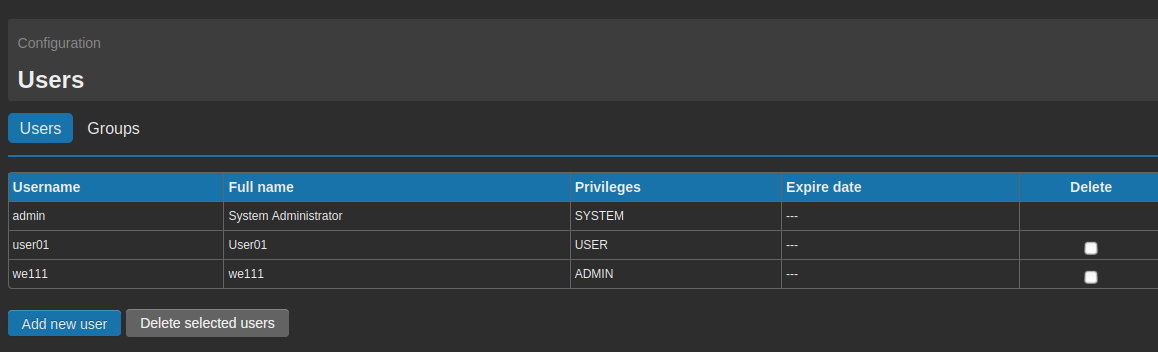
In order to allow a user to send commands to the device, the relevant option on the page modify/create user must be enabled (see 8. Users).
Note
In case of Emails, the command to be sent to the device must be included on the subject of the email and not in the body.
4.2. Actions
If the condition specified in the event is fulfilled, the WE151 can perform actions.
The actions can be used to perform automated logics, to notify an alarm condition to one or more users, and to let the device connect to others.
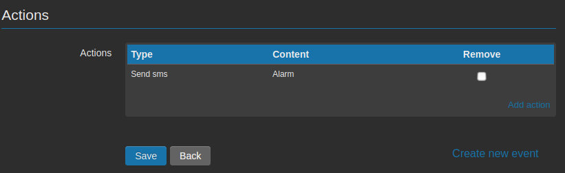
Once created an event and clicked on Save, a new section called Actions with relevant link Add action.
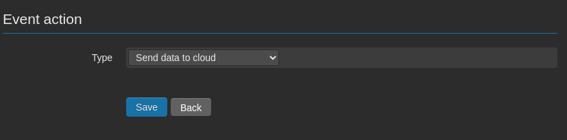
Clicking on the link, we enter a new page
From this page it’s possible to create an action for the just defined event. The available actions are:
- Send Email
- Send Chat
- Send SMS
- Execute a Command
- Send data to cloud
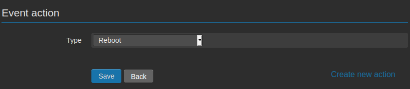
- Reboot
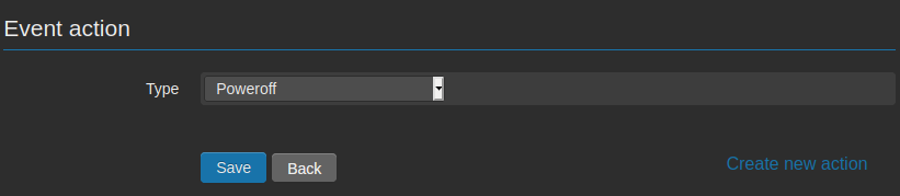
- Poweroff
Through the fields Execute action each and Minutes/Hours it’s also possible to configure that the action is repeated at regular time intervals untill the event remains active.
Once created an action, it’s possible to find it on the list available under the event. It’s possible to create up to 5 actions for each single alarm.
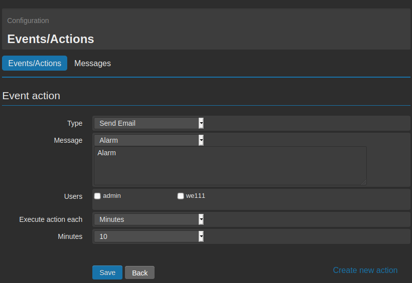
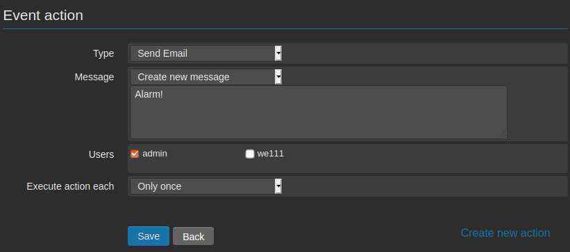
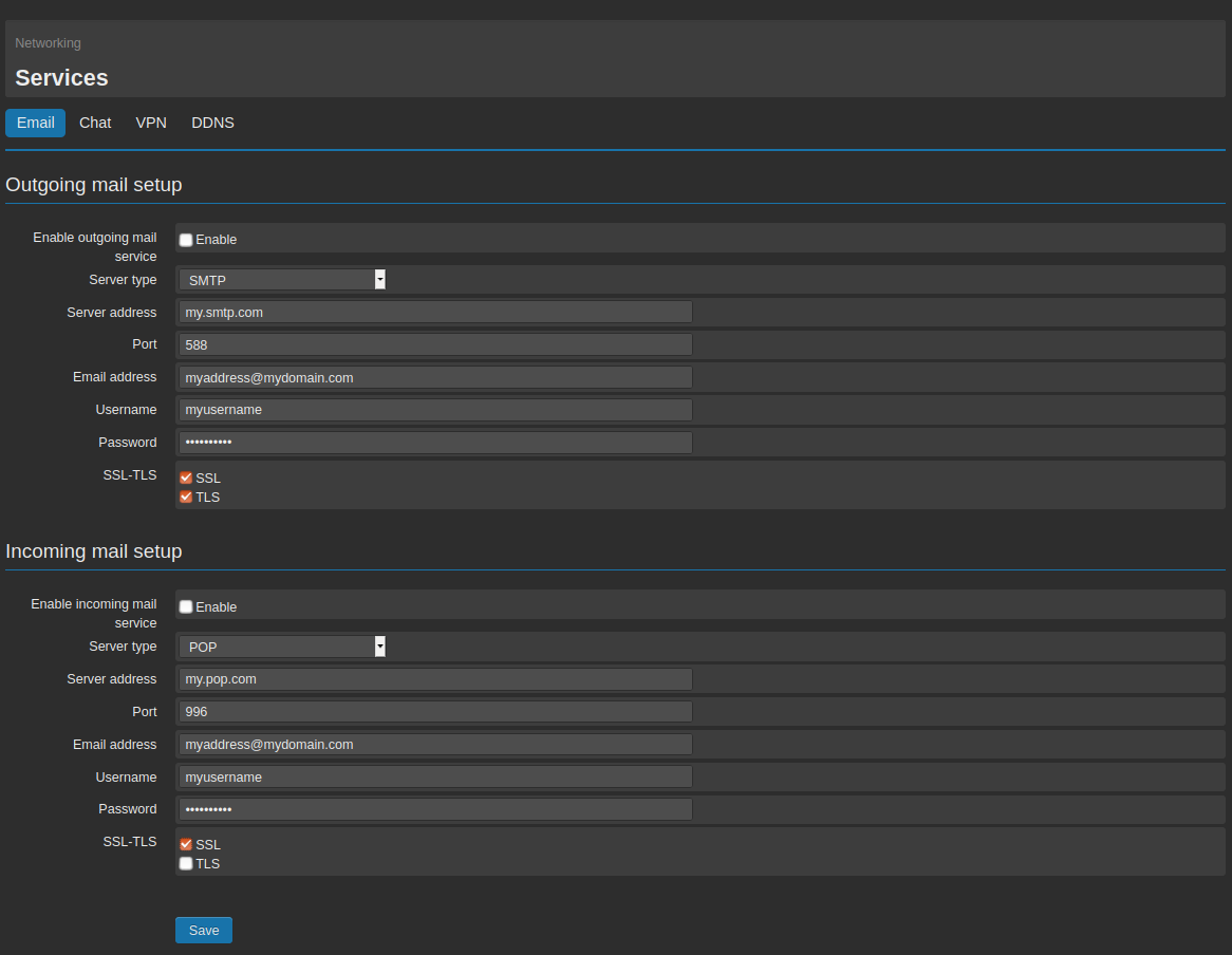
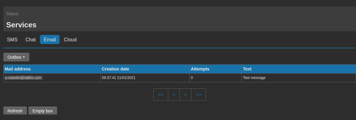
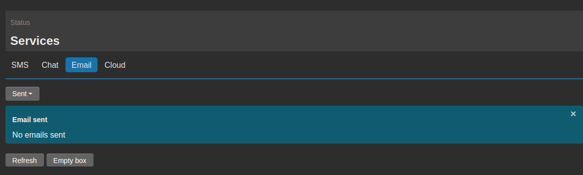
4.2.1. Action Send Email
Selecting the option Send Email, it’s possible to write the text to be sent in case the event should occur.
If previously used messages are available, it’s possible to choose among them on the field Message through the drop down menu.
On the other hand, if a new text has to be created, it’s possible to select Create new message.
To modify an existing message, enter the page Configuration → Events/Actions → Messages and select the message to be modified.
Once defined the message, it’s possible to select the receivers among the list of registered users and groups.
Beside the definition of the event and the action, that should trigger the email to a certain user, it’s necessary to consider also the following:
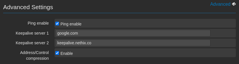
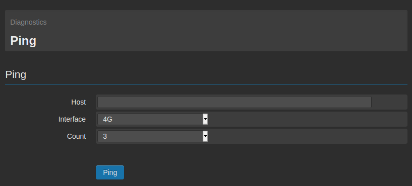
- The internet connection must be active (see 9. Connectivity and 11.3. Ping).
- The selected user/s must be enabled to receive notification emails and shall have confirmed a valid email address (see section 8. Users).
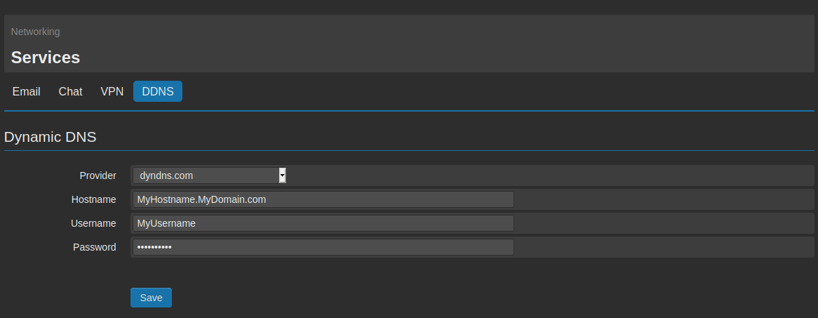
- The mail service shall be properly configured (see section 9.3. Email).
All the texts used for the different actions can be found on the page Configuration → Events/Actions → Messages.
From this page it’s possible to delete the messages, using the relevant tab and clicking on Delete, or edit one or more messages by clicking on them.
On the messages to be sent at the occurrence of a certain event, it’s possible to recall the value of one or more variables.
For this option is necessary to write on the message the symbol $ followed by the name of the variable (respecting upper and lower case):
EXAMPLE:
If we have a variable called Var1 and we want to recall the value within the message for threshold crossing:
Text to be configured:
Alarm for high level. The level is $Var1 meters
if at the moment of the message sending the variable has a value of 5.7:
The message will be:
Alarm for high level. The level is of 5.7 meters.
Within one message is possible to recall more than one variable’s value.
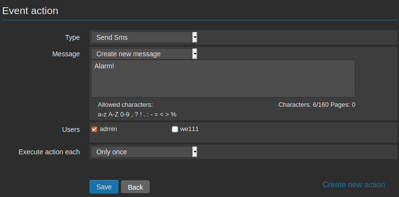
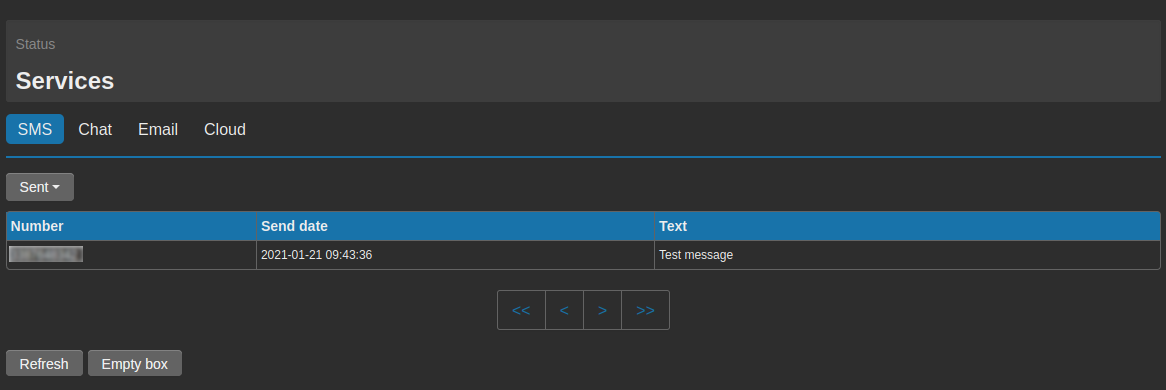
4.2.2. Action Send SMS
Selecting Send SMS, it’s possible to write the text to be sent in case the event should occur.
If previously used messages are available, it’s possible to choose among them on the field Message through the drop down menu.
On the other hand, if a new text has to be created, it’s possible to select Create new message.
To modify an existing message, enter the page Configuration → Events/Actions → Messages and select the message to be modified.
Once defined the message, it’s possible to select the receivers among the list of registered users and groups.
Beside the definition of the event and the action, that should trigger the SMS to a certain user, it’s necessary to consider also the following :
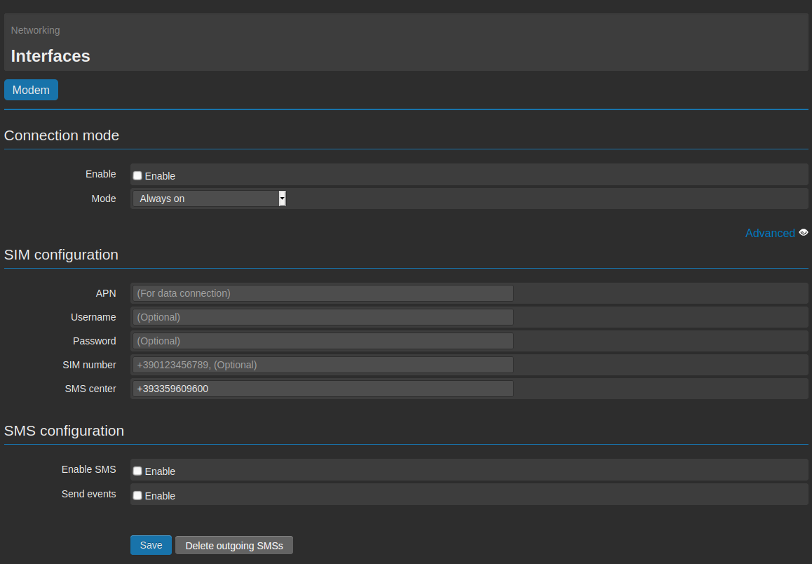
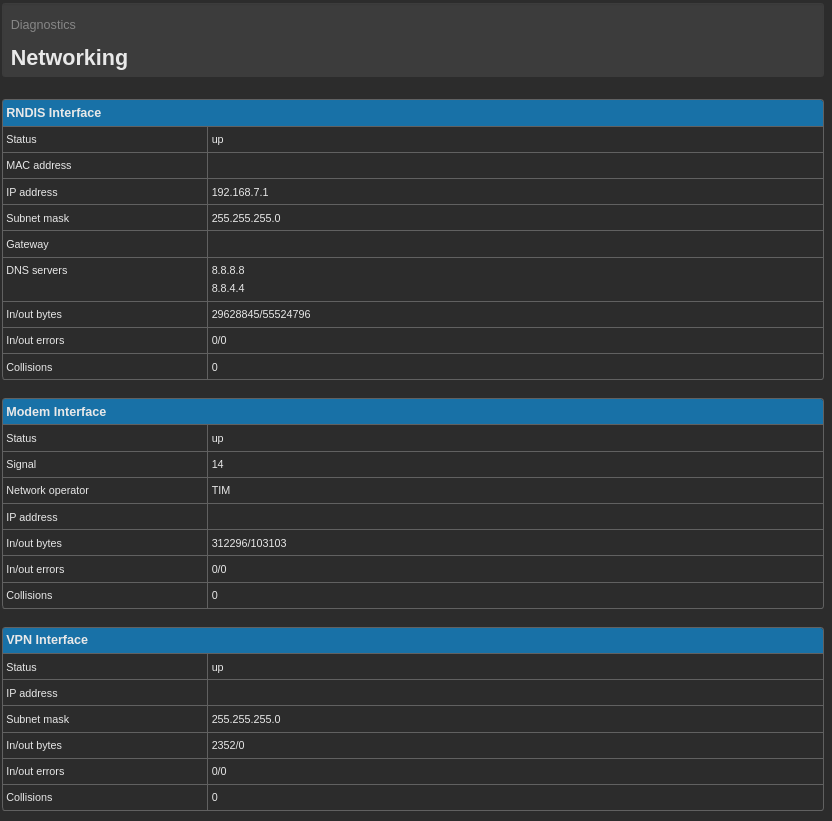
- The signal coverage should be enough (displayed on the status panel on the right side of the interface).
- The user/s must be enabled to receive SMS notifications and shall be associated to a valid telephone number (see section 8.1. Create a new user).
- The SMS service must be properly configured (see section 9.1.1. Data connection and SMS).
All the texts used for the different actions can be found on the page Configuration → Events/Actions → Messages.
From this page it’s possible to delete the messages, using the relevant tab and clicking on Delete, or edit one or more messages by clicking on them.
On the messages to be sent at the occurrence of a certain event, it’s possible to recall the value of one or more variables.
For this option is necessary to write on the message the symbol $ followed by the name of the variable (respecting upper and lower case)
EXAMPLE:
If we have a variable called Var1 and we want to recall the value within the message for threshold crossing:
Text to be configured:
Alarm for high level. The level is $Var1 meters
If at the moment of the message sending the variable has a value of 5.7
The message will be:
Alarm for high level. The level is of 5.7 meters
Within one message is possible to recall more than one variable’s value.
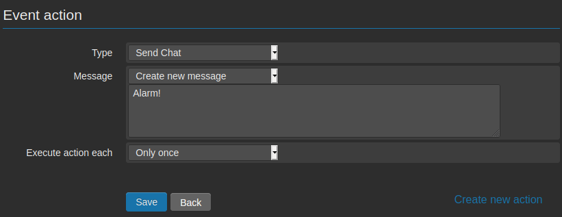
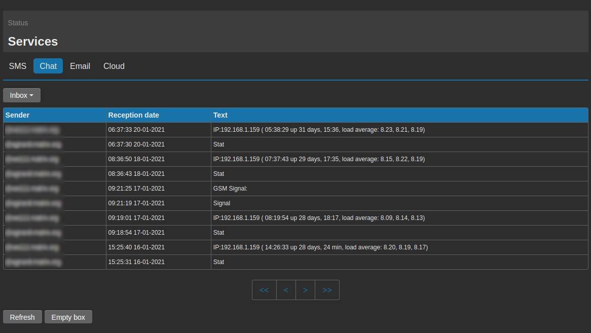
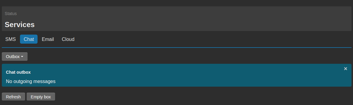
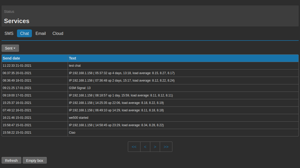
4.2.3. Action Send Chat
Selecting Send Chat, it’s possible to write the text to be sent in case the event should occur.
If previously used messages are available, it’s possible to choose among them on the field Message through the drop down menu.
On the other hand, if a new text has to be created, it’s possible to select Create new message.
To modify an existing message, enter the page Configuration → Events/Actions → Messages and select the message to be modified.
Once defined the message, it’s possible to select the receivers among the list of registered users and groups.
Beside the definition of the event and the action, that should trigger the message via Chat to a certain user, it’s necessary to consider also the following :
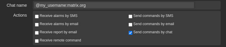
- The selected user/s shall be enabled to receive chat messages and shall have associated a valid chat name (see section 8.1. Create a new user).
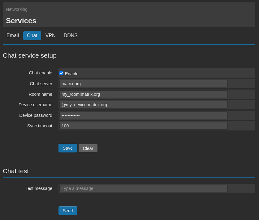
- The Chat service must be properly configured (see section 9.4. Chat).
- The device must be connected to the internet (see sections 9. Connectivity and 11.3. Ping).
All the texts used for the different actions can be found on the page Configuration → Events/Actions → Messages.
From this page it’s possible to delete the messages, using the relevant tab and clicking on Delete, or edit one or more messages by clicking on them.
On the messages to be sent at the occurrence of a certain event, it’s possible to recall the value of one or more variables.
For this option is necessary to write on the message the symbol $ followed by the name of the variable (respecting upper and lower case).
EXAMPLE:
If we have a variable called Var1 and we want to recall the value within the message for threshold crossing:
Text to be configured:
Alarm for high level. The level is $Var1 meters
If at the moment of the message sending the variable has a value of 5.7
The message will be:
Alarm for high level. The level is of 5.7 meters
Within one message is possible to recall more than one variable’s value.
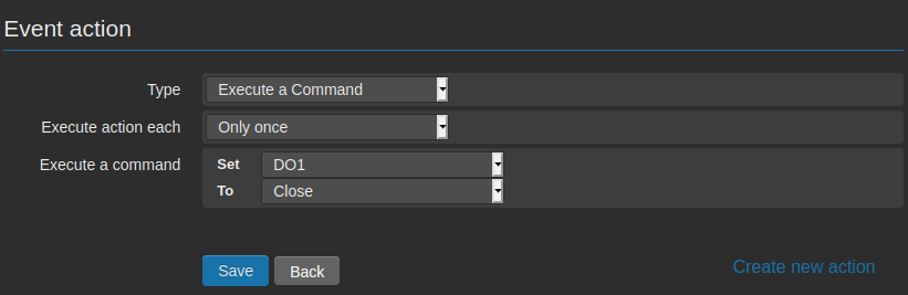
4.2.4. Action Execute a Command
Selecting Execute a Command from the field Type, it’s possible to select a variable among those available in the list and define then a value on the field To.
Thus at the occurrence of the defined event, the selected variable will be set at the value entered in the field To.
Inside the drop down menu Set may not be available all the created variables, because the system automatically select the variables that may have the value changed:
- Variable type DO
- Variable type Virtual
- Variable type Modbus write
- Variable type Modbus read/write
For obvious reasons the following variables won’t appear in this list:
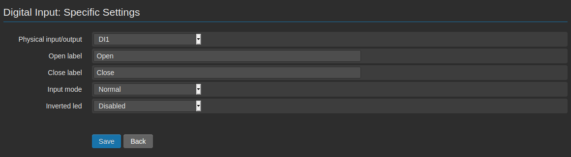
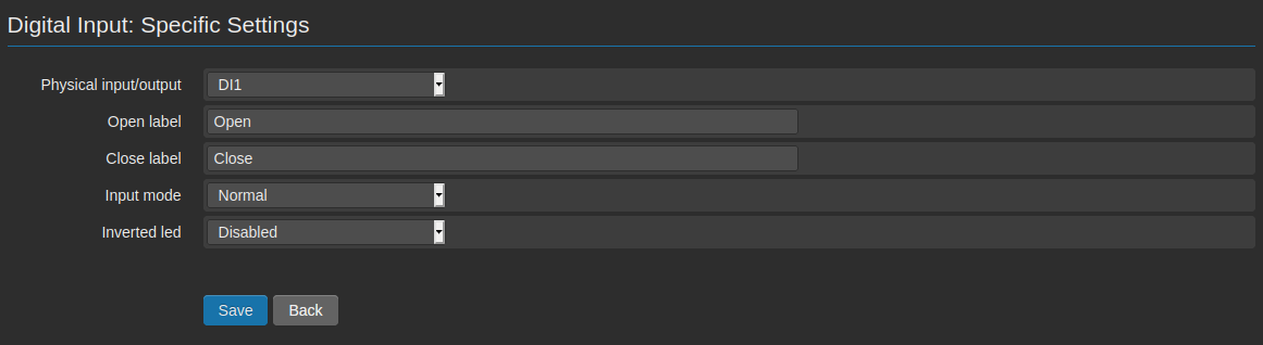
- Variables type DI
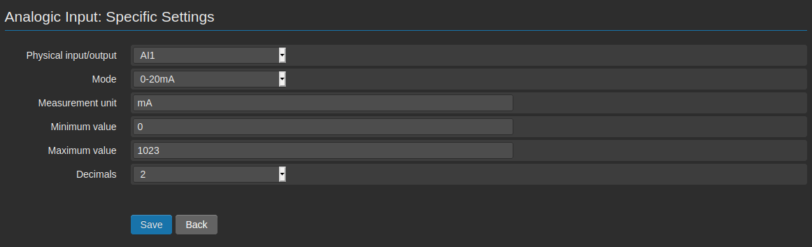
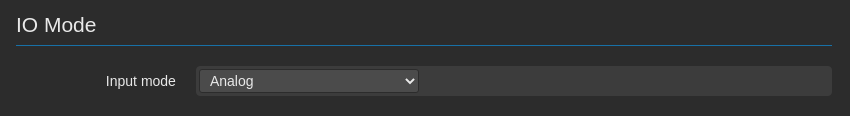
- Variables type AI
- Variables type Modbus read
Through an action type Execute a Command, it’s possible to create automated operations connected to the occurrence of a certain event, as for instance the closing of an output if an analog input should reach a certain threshold.
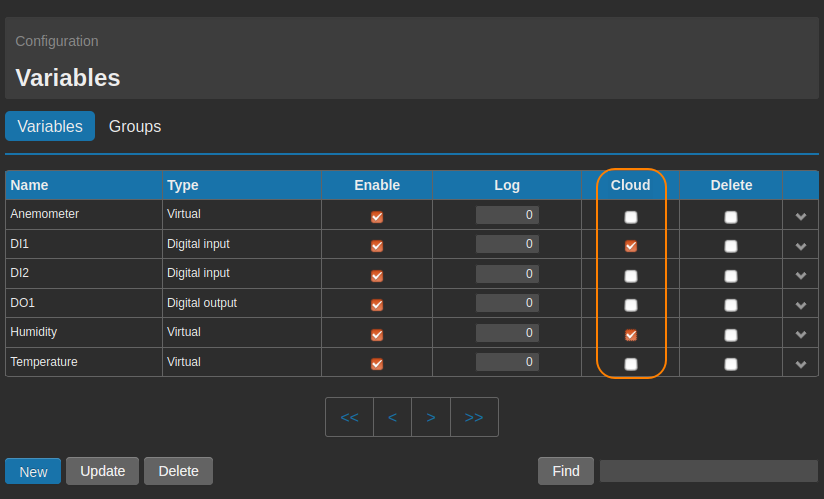
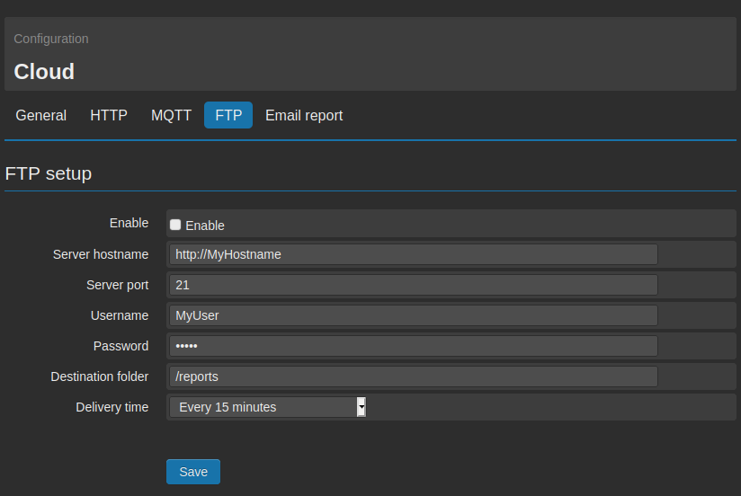
4.2.5. Action Send data to cloud
Selecting
Send data to cloud on the field
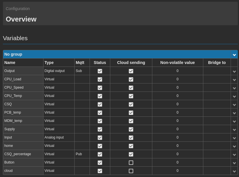
Type, at the occurrence of a certain event, it will be sent to the cloud the status of those variables, where the option
Cloud sending is enabled (see section
2.1. Generic Settings).
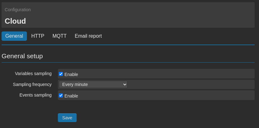
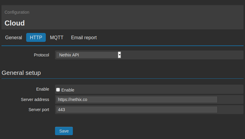
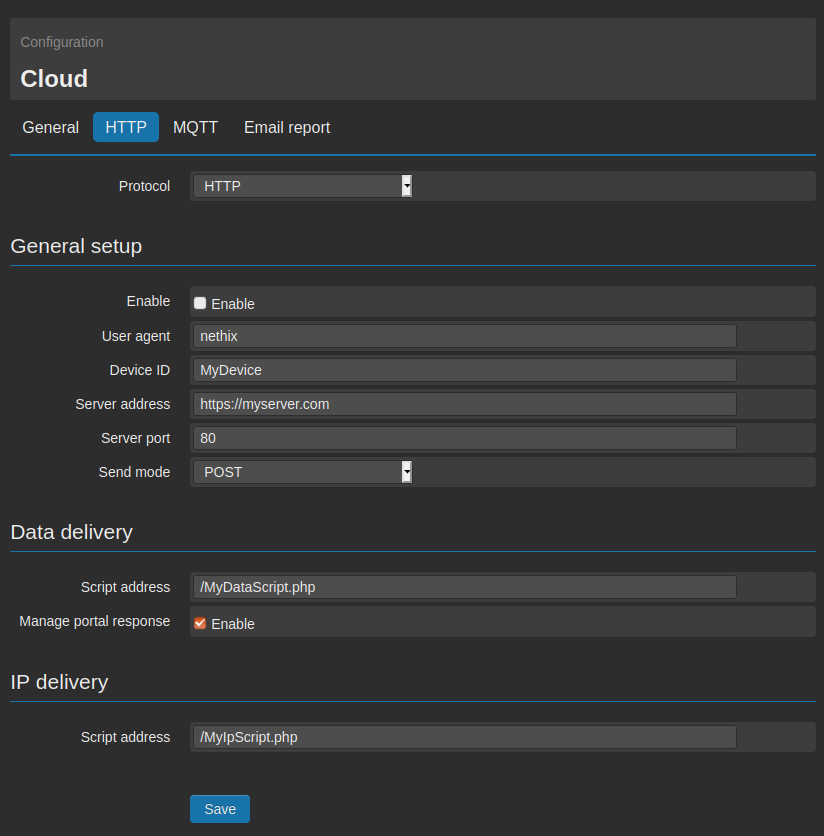
The variable value will be immediately sent to the cloud, as selected on the page
Configuration → Cloud → General (see section
7.3. HTTP/S).
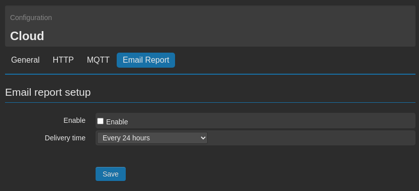
If the data delivery by email report is enabled (see section
7.6. Email report), a new line will be generated, containing the status of the variables at the time.
In this case (and FTP too, see
7.7. FTP/S) the delivery won’t be immediate, but according to the timing set by the user.
4.2.6. Action Reboot
Selecting Reboot on the field Type, it’s possible to let the WE151 reboot at the occurrence of the associated event.
4.2.7. Action Poweroff
Selecting Poweroff on the field Type, it’s possible to let the WE151 power off at the occurrence of the associated event.
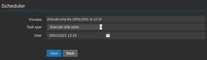
 available at the right of the field Date, the scheduler is opened and it allows to define the hour, the day, the month and the year, when the action has to be executed.
Once executed the action, the event can be deleted, since it has to be executed only once.
available at the right of the field Date, the scheduler is opened and it allows to define the hour, the day, the month and the year, when the action has to be executed.
Once executed the action, the event can be deleted, since it has to be executed only once.
 or gray
  , according to the status and the configuration of the variable.
 shows that no alarms are activated. The icon
  shows instead the presence of an event, configured as an alarm.

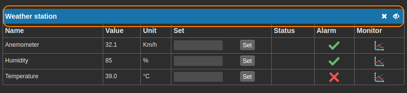
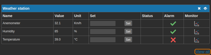
 that allows to expand the contents and access to further details.
 The product shall not be treated as household waste. It shall be instead handed over to an appropriate collection point for the recycling of electrical and electronic products. For further information about recycling of this product, contact the local city office and/or the local waste disposal service.