Quick start guide
1. Overview
This document gives all necessary information for starting-up the device.
Further information regarding the configuration and the functionalities of the WE120 are available on the official instruction manual of the WE120.
2. SIM card insertion
- If the SIM Card uses a PIN code, insert the SIM card into a GSM mobile phone and disable the PIN code.
- No further operation is required for the SIM card. It’s not necessary to add contacts on the SIM phone-book, since the WE120 can manage them automatically
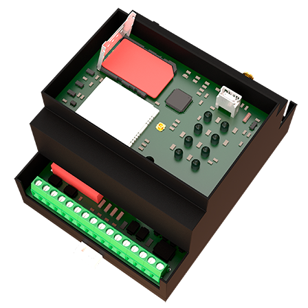
- Lift the upper panel of the WE120 from one side using a screwdriver. Operate carefully and with a thin tool to avoid damages on the plastic case.
- Unlock the SIM holder connector moving the sliding holder in the direction indicated for OPEN.
- Lift the sliding holder and insert the SIM in the housing, paying attention to the correct positioning of the card.
- Close the sliding holder to block the connector, moving it in the direction indicated for LOCK.
- Reinstall the upper panel of the WE120.
- Screw the antenna into the relevant connector.
Warning
Make sure that the device is turned off before inserting the SIM card.
3. Configuration
The WE120 can be configured in three different ways:
The easiest way for configuring the device is through the App that can be downloaded from here:

3.1 Configuration example using SMS
The following example shows a typical configuration session and use of the WE120 through SMS.
The following text on gray background has to be edited as SMS on any mobile phone and sent to the SIM card number inserted in the WE120.
- Clear the device’s memory
- Set the SMS Service Centre number (according to the designated Provider- the following example refers to Vodafone Italy)
CENTER 0000 +393492000200
- Add new administrator user that will be authorized to receive messages and alarms sent from the device
ADD 0000 +39493213213 Admin 3 1
- The WE120 is now configured and ready for use. Send the following commands from the administrator number to verify proper operation of the system. Send the following message to close relay n.1. Check that the status LEDs change.
- Send the following message to open relay n.1. Check that the status LEDs change.
- Read WE120 status. The device replies an SMS with all the I/O status information.
- Request the users list. The device replies an SMS with the list of registered users.
For a more comprehensive description of the available commands and relevant syntax see the manual’s 6. Command description section.
4. Firmware update
It is highly recommended, before start using the device, to update to the latest firmware using the
Genesys 3 application. The firmware update procedure does not overwrite nor cancels the device configuration.
The update procudure is described in the Firmware Update guide.
5. Mounting
- Mount the device on a standard DIN rail, paying attention to the accessibility of the SIM card. Make sure that the GSM network signal has sufficient strenght (verify it with a mobile phone).
- Connect to the Digital input terminals a dry contact, like a relay, a switch or similar. Do not connect live voltages to avoid damages on the WE120.
- Connect to the RL terminals the load that has to be activated/controlled by the WE120.
- Connect the analogue inputs to the desired analogue signals. See DIP SWITCH section for further instructions about how to change the configuration of the analog inputs.
- Connect the required power source to the terminals signaled as
 .
.
6. Switching on
- Make sure that the WE120 is properly connected, as described above.
- Power the WE120
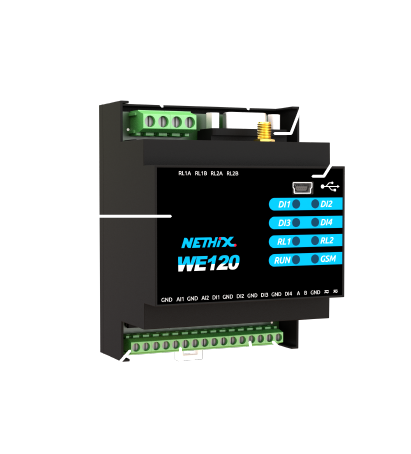
- The device takes some seconds for the initialization. During this phase the GSM LED blinks fast. After some time the RUN LED is switched on. Initialization ends with a GSM signal check. The LEDs DI1, DI2, DI3, DI4, RL1 and RL2 blink five times showing the signal level, as described below:
- NO LED blinking: NO GSM signal (*)
- 1 LED blinking : very low GSM signal (*)
- 2 LEDS blinking: low GSM signal
- 3 LEDS blinking: medium GSM signal
- 4 LEDS blinking: good GSM signal
- 5 LEDS blinking: very good GSM signal
- 6 LEDS blinking: very good GSM signal
- After the initialization, the WE120 is ready for normal operation. The GSM and RUN LEDs are blinking. The DI1, DI2, DI3, DI4 LEDs show the status of the digital inputs and RL1, RL2 indicate the status of the relay outputs.
It’s now possible to interact with the WE120 through SMS in order to activate outputs and monitor the status of the inputs, or to send configuration SMS.
Warning
(*) If less than two LEDs are blinking, the GSM signal is weak and the connectivity may not work properly.