2. Variables management
A variable contains the value of a monitoring/control parameter of the system. For instance a variable called temperature could be the value of the environmental temperature measured by an analog probe.
WE111 allows to create variables, suitable to define events and actions. The variables are relevant elements of the system, since they include the values of measured or monitored parameters and allow to manage alarms notifications or data delivery to portal or cloud.
The variables and their status are available at the page Status → Variables and can be displayed in alphabetical order or in groups.
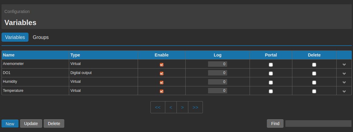
For the creation or modification of a variable, it’s necessary to go to the page Configuration → Variables → Variables.
In case of already defined variables, these will be shown on a tab, where the most important information are visualized. On this tab is possible to disable a variable (and its associated events/actions), to cancel it, to enable or disable the data delivery to portal and the dataloggin function, or to create a new variable clicking on New.
For a fast research of one or more variables, it’s possible to use the field Find.
2.1. Generic Settings
Several variable types are available, having different parameters. Only the section Generic Settings is valid for any type of variable. This section is composed of the following fields:
- Name: it’s the name to be assigned to the variable. All alphanumeric characters and the character ”_” are supported.
- Type: it allows to select the variable type. For each type of variable the parameters to be set are different: to this regard see chapter 2.2. Type.
- Variable status: enable/disable the variable.
- Cloud sending: it allows to enable/disable the sending of the variable value to a portal or external server. For further information regarding the datadelivery, see the dedicated section 6. Data delivery.
- Non-volatile value: it allows to save the value of the variable every X minutes and every time the device is rebooted or switched off via software. Setting the value at 0, the status of the variable won’t be restored after a reboot/poweroff.
- MQTT mode: it allows to select the way of interfacing to a broker MQTT (see section 6.4. MQTT/S for further specifications about this function).
2.2. Type
The available types of variables to be defined are the following:
- Analog input: associated to the input on board, selectable only if configured as analog input. Further information available on paragraph 2.3. Variable Analog Input (AI).
- Digital input: associated to the input on board and selectable only if configured as digital input. Further information available on paragraph 2.4. Variable Digital Input (DI).
- Digital output: associated to the digital output (relay) of WE111. Further information available on paragraph 2.5. Variable Digital Output (DO).
- Virtual: these are virtual variables, that can be created to manage alarms, formulas, to report the status of the system variables or other. Further information available on paragraph 2.6. Virtual Variables.
2.4. Variable Digital Input (DI)
In order to create a varible type DI, it’s first of all necessary to configure the input properly (see 11.1. Input configuration).
Once configured the input as Digital Input, enter the page Configuration → Variables. Click then on the tab New.
Select Digital Input under the position Type.
Inside the section Generic Settings you can find the general settings suitable for all variable-types. The description of all the fields of this section are available at 2.1. Generic Settings.
We proceed then to the section called Digital Input: Specific Settings.
From the field Input mode, select the desired modality among the following options:
- Normal
- Counter
- Flow measurement
- Time counter
According to the selection made, the following fields will have different meaning.
2.4.1. Normal
A variable type DI → Normal is a variable that allows to display the status of the digital contact. It’s therefore possible to define events/actions according to the contact changing (open>closed and viceversa)
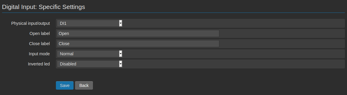
A so called Normal digital input can be open or closed. Thanks to the fields Open label e Close label it’s possible to associate a string, that will be displayed on the page Status → Variables, in order to intuitively show to the user the current status of the input.
For WE111, the input has to be considered closed when it’s bridged to GND; it’s open when there’s no connection between the input and GND.
The only further field to be configured is Inverted led. This setting influences the visualization of the variable on the page Status → Variables. If the option is disabled, the input status Open shows a gray icon, while the status closed shows a green icon. If the option is enabled, the visualization will be the opposite. For further details see relevant section 5.1. Variables status.
Note
During the configuration of events/alarms, the input status Closed corresponds to value 1, while the status Open corresponds to 0.
2.4.2. Counter
A variable type DI → Counter is a variable that allows to count the pulses on a digital input.
The first field to be filled is Count start i.e. the starting point of the counter. This value will be considered only the first time. If the counter is reset, this will restart from 0.
Counter end it’s the maximum limit to be reached to reset the counter. If this field is at 0, the counter will continuously increment and never reset.
Count increment it’s the increment unit of the counter at every impulse. The quantity entered in this field will be added to the current value at every impulse.
Measurement unit it’s the measurement unit assigned to the counter. It will be displayed on graphs and on the page Status → Variables.
The last setting is the Edge trigger, the edge to be considered as an impulse:
- Falling edge: the counter increments when the input gets from closed to open.
- Rising edge: the counter increments when the input gets from open to closed.
- Rising and falling edge: the counter increments at every status changing of the input.
2.4.3. Flow measurement
A variable type DI → Flow measurement is a variable that allows, for instance, to calculate the flow rate.
On the field Timeout is edited the maximum time interval (in seconds) between two pulses. After the set time has expired, the variable will be reset.
It’s useful to set the timeout, in case the flow should stop. In this case, if the timeout is not set, the value of the variable would remain the one of the last received pulse, thus giving a wrong information and creating potentially contradictory logs.
Inside the field Volume is set the sample unit to be associated to a pulse.
Measurement unit allows to set a measurement unit for this variable, on the other hand on Edge trigger is possible to select the edge to be considered as a pulse:
- Falling edge if it has to be considered the switch from closed to open.
- Rising edge if it has to be considered the switch from open to closed.
- Rising and falling edge edge if both edges have to be considered.
EXAMPLE:
If we set the timeout at “600” (seconds), the Edge trigger as Rising edge, the measurement unit as L/s (i.e. liter per second) and the volume at 100, we will have the following:
- The input changes from open to closed, WE111 starts counts the time
- The input changes from closed to open
- The input changes from open to closed after 20 seconds
- WE111 divides the sample volume (100) for the time passed (20 seconds) and will display 5L/s
- The input doesn’t change its status for at least 600 seconds.
- WE111 resets the variable and waits for new pulses before starting counting again.
2.4.4. Time counter
A variable type DI → Time counter è una variabile che permette di contare il tempo (in secondi) is a variable that allows to count the time ( in seconds) of opening/closing of a contact; this application is interesting for example to get the total operating time of a machinery.
After the selection of the Edge trigger o be considered (please remind that Falling edge is the changing from closed to open, Rising edge is the contrary and Rising and falling edge both of them), it’s necessary to select the type of counter. These are the options:
- Permanent: after starting the counting, WE111 will increment the value at every second, until the user will reset it.
- Stop on opposite edge: the counting starts at the edge changing, compatible with the selection made on Edge trigger, it stops when the opposite edge is reached and will start again when the selected edge is reached.
- Reset on opposite edge: the counting is reset when it reaches the opposite edge, and will start again from 0 when the edge defined on Edge trigger is reached again.
2.5. Variable Digital Output (DO)
To create a DO variable, associated to a digital output available on board of the device, it’s first of all necessary to enter the page Configuration → Variables. Clicking on the tab New, we get to the page , where it’s possible to configure the variable.
Under the position Digital Output select Type.
Inside the section Generic Settings you can find the general settings suitable for all variable-types. The description of all the fields of this section are available at 2.1. Generic Settings.
On the section called Digital Output: Specific Settings, it’s required to configure the operating modality on the field Output mode.
Le opzioni disponibili sono:
- Normally open: normally open operating. Open label corresponds to the open status of the contact. Close label closes the contact.
- Normally close: normally closed operating. Open label corresponds to the open status of the contact. Close label closes the contact.
- Pulse open: pulse mode operating. Open label corresponds to the open status of the contact. Close label closes the contact. If the output is closed, it remains in this status for the time set on the field Pulse Duration and then get back to the previous open status.
- Pulse closed: pulse mode operating. Open label corresponds to the open status of the contact. Close label**closes the contact. If the output is closed, it remains in this status for the time set on the field **Pulse Duration and then get back to the previous open status.
Independently from the selected option, on the field Status change delay (s) must be entered the number of delay seconds, before the output is activated or deactivated at any impulse coming.
Please note that the option Non-volatile value can be combined with the Output mode.
If the option is disabled, the status of the output at the start (after a shut down or reboot) will depend directly on the Output mode, in case the output is Normally open/Pulse open, the contact will start in open status; if the output is Normally closed/Pulse closed, the contact will start in closed status.
If, on the other hand, the Non-volatile value option is enabled, at the start up of the system it will be restored the previous output status.
The status of the digital outputs can be modified by associating them to an event, through a dedicated command via SMS, Chat, Email or directly from Status → Variables.
2.6. Virtual Variables
Virtual variables are not connected to the I/O of the device and can be of different types.
The status of a virtual variable can be modified/read via SMS, Chat, Email from the page Status -> Variables or at the occurrence of an event, and its value can be given also by a mathematical formula.
Some virtual variables allow to monitor the system parameters or to change remotly the threshold of an alarm/event (for example a setpoint).
Others can be used to let WE111 manage the status or the value coming from a measurement, made by a different device (Nethix or not, through MQTT protocol)
To create a variable type Virtual, it’s first of all necessary to enter the page Configuration → Variables. Clicking on the tab New, we enter the page, where it’s possible to configure the variable.
Select Virtual under the position Type.
Inside the section Generic Settings you can find the general settings suitable for all variable-types. The description of all the fields of this section are available at 2.1. Generic Settings.
On the section called Virtual variable: Specific Settings, is given the possibility to choose among the following options:
- Normal
- Math expression
- Date/time
- System variables
2.6.1. Normal
Selecting the type Normal, the Measurement unit and the Decimals numbers have to be entered on the relevant fields.
The value of this type of variable can be changed manually (SMS, Email, Chat or from Status → Variables) and/or automatically (through the action execute command configurable on the page for the events creation 3.2.4. Action Execute a Command).
2.6.2. Math expression
Selecting the type Math expression , beside the Measurement unit and the Decimals numbers, it’s possible to specify also the math expression to be applied to the variable.
A Virtual variable → Math expression allows to make calculations using constants or variables as elements, and gives the possibility to use some of the most common mathematical operations such as:
- Addition (+)
- Subtraction (-)
- Multiplication (*)
- Division (/)
- Exponentiation (^)
- Square Root (sqrt)
- Logarithm (log)
- Sine (sin)
- Cosine (cos)
beside other constants as:
- e (e)
- base 2 logarithm of e (log2e)
- base 10 logarithm of e (log10e)
- square root of PI (2_sqrtpi)
- square root of 2 (sqrt)
- square root of 1/2 (sqrt1_2)
The use of round brackets is supported.
EXAMPLE 1:
“Var1” is the name of a variable of any type (not necessarily Virtual) and its value is 10.
On the field Math expression we could write:
Var1^2
In this case the Virtual variable would assume value “100”.
EXAMPLE 2:
Var1 is as for previous example, Var2 is another variable of any type having value 15.
On the field Math expression we could write:
( Var1 * ( Var2 – 10 ) ) / 2
From which we get: (10 * (15-10)) / 2 → (10*5)/2 → 50 / 2 → 25
The value displayed by WE111 would then be “25”.
At every changing of one of the expression’s factors, the result is immediately recalculated by WE111.
A Virtual variable type Math expression can be used as an element inside another expression.
2.6.3. Date/time
Selecting Date/Time the variable will show the value in seconds, minutes, hours, day of the month, month, year, day of the week o day of the year.
For example, selecting Minutes [0-59] on the field Date/time mode at 12:35 the variable will show the value 35.
2.6.4. System variables
Selecting System variables it’s possible to specify the Measurement unit and the Decimals numbers, this type of variables can represent:
- GSM CSQ (signal strength of the Provider)
- CPU Load (load of the CPU)
- CPU Speed (speed of the CPU)
- CPU Temperature (temperature of the CPU)
- Free Memory (available memory)
- PCB Temperature (temperature of the PCB)
- Modem Temperature (temperature of the Modem)
- V Supply (supply tension)
- Button (status of the button: it’s possible to define an event when it’s pressed)
As for all other variables, also for the system variables it’s possible to associate one or more alarm conditions.
2.7. Bridge between variables
WE111 allows to create a bridge between variables, in order to transfer the value or the status from a variable to another.
If, for example, we want to read the value of the analog input and transfer it to a virtual variable, this is the procedure:
- Select from the Available variables menu the virtual variable previously created.
Through this procedure we will get 2 variables having the same value. At every changing of the status/value of the variable type Analog Input will correspond the changing of the value of the variable virtual.
3. Events/Actions
The events and actions allow to set the conditions for alarms or notifications, according to the value or status of a variable.
The event is the necessary condition to generate an action.
Actions allow to trigger automated logics, to communicate with other devices, to send SMS notifications, Emails, Chat and other.
Before creating Events/Actions, it’s necessary to have variables.
3.1. Events
The events allow the WE111 to get aware, when a monitored parameter has crossed a certain threshold, set by the user.
There are different types of events, and for every type there are several parameters, that allow to have high flexibility in the monitoring and control of a system.
To create an event, it’s necessary to get to the page Configuration → Events/Actions → Events/Actions and then click on the tab New.
The tab Delete allows to delete one or more selected events, while with the tab Update it’s possible to make some modifications as for instance to able/disable one or more events, or to notify them as alarms and send them to a web portal.
In order to recall one or more events, it’s possible to use the field Find that allows to make a query based on name.
When an event is created, after assigning a name, it’s necessary to confirm the type of event among Variable, Incoming data or Scheduler (see 4. Scheduler).
There are a few generic options that can be enabled according to the selected event’s type: it’s possible to decide wether to enable the event from Status or not, wether to display it or not as an alarm from the field Set as alarm and wether to send it or not to a web portal from the field Send to portal.
In case the option Set as alarm is enabled, at the occurrence of the event a red “X” will appear on the page Status → Variables, near the name of the variable (on the column Alarm); this allows to see at a glanace the presence of a critical condition.
The option Send to portal allows on the other hand to send an event to a web portal. At the occurrence of the event, the WE111 will execute the associated actions and send to portal a string, containing the name of the event and further relevant information.
3.1.1. Events on variables
It’s an event that occurs when a variable reaches a certain value or a certain status.
The behaviour of this type of event is determined by the behaviour of the variables, that will be associated to it.
First of all it’s necessary to choose a variable from the field Variable.
From the drop down menu, it’s possible see all variables previously created and select the one, on which an event has to be configured.
The second parameter to be selected is the one connected to the Condition. The possible options are EQUAL, NOT EQUAL, GREATER THAN, GREATER OR EQUAL THAN, LESS THAN and LESS OR EQUAL THAN.
It’s necessary to set the value to be considered as threshold for triggering the event, on the selected variable, entering a numerical value on the field Value.
It’s possible to set a delay on the field Delay. The value is expressed in seconds and it avoids that the event is triggered immediately.
The variable Value must remain under the defined condition (Condition) for a time not shorter than the one configured in Delay, before the defined event is finally considered activated and the associated actions are executed.
It’s also possible to set that an event (and its associated actions) are ignored, if it’s found activated after a shut down/reboot of the system. This is possible enabling the option Skip action at startup.
3.1.2. Incoming data
The incoming events are those triggered by inputs coming from external sources:
This function gives the possibility to create customized commands to be sent to the device. The commands could be sent by users or other devices.
After the selection of the desired option from the field Data source, it has to be entered the text of the command (to be entered on the field Message).
On the field Users can be eventually selected the users or the groups of users enabled to send the command.
The actions associated to such an event will be then executed at the receipt of the text, as entered on the field Message, on condition that it’s sent by one of the selected users.
Note
The commands must be written case sensitive, as originally entered in the configuration.
Note
In order to allow a user to send commands to the device, the relevant option on the page modify/create user must be enabled (see 7. Users).
Note
In case of Emails, the command to be sent to the device must be included on the subject of the email and not in the body.
3.2. Actions
If the condition specified in the event is fulfilled, the WE111 can perform actions.
The actions can be used to perform automated logics, to notify an alarm condition to one or more users, and to let the device connect to others.
Once created an event and clicked on Save, a new section called Actions with relevant link Add action.
Clicking on the link, we enter a new page
From this page it’s possible to create an action for the just defined event. The available actions are:
- Send Email
- Send Chat
- Send SMS
- Execute a Command
- Send data to cloud
- Reboot
- Poweroff
Through the fields Execute action each and Minutes/Hours it’s also possible to configure that the action is repeated at regular time intervals untill the event remains active.
Once created an action, it’s possible to find it on the list available under the event. It’s possible to create up to 5 actions for each single alarm.
3.2.1. Action Send Email
Selecting the option Send Email, it’s possible to write the text to be sent in case the event should occur.
If previously used messages are available, it’s possible to choose among them on the field Message through the drop down menu.
On the other hand, if a new text has to be created, it’s possible to select Create new message.
To modify an existing message, enter the page Configuration → Events/Actions → Messages and select the message to be modified.
Once defined the message, it’s possible to select the receivers among the list of registered users and groups.
Beside the definition of the event and the action, that should trigger the email to a certain user, it’s necessary to consider also the following:
- The internet connection must be active (see 8. Connectivity and 10.3. Ping).
- The selected user/s must be enabled to receive notification emails and shall have confirmed a valid email address (see section 7. Users).
- The mail service shall be properly configured (see section 8.3. Email).
All the texts used for the different actions can be found on the page Configuration → Events/Actions → Messages.
From this page it’s possible to delete the messages, using the relevant tab and clicking on Delete, or edit one or more messages by clicking on them.
On the messages to be sent at the occurrence of a certain event, it’s possible to recall the value of one or more variables.
For this option is necessary to write on the message the symbol $ followed by the name of the variable (respecting upper and lower case):
EXAMPLE:
If we have a variable called Var1 and we want to recall the value within the message for threshold crossing:
Text to be configured:
Alarm for high level. The level is $Var1 meters
if at the moment of the message sending the variable has a value of 5.7:
The message will be:
Alarm for high level. The level is of 5.7 meters.
Within one message is possible to recall more than one variable’s value.
3.2.2. Action Send SMS
Selecting Send SMS, it’s possible to write the text to be sent in case the event should occur.
If previously used messages are available, it’s possible to choose among them on the field Message through the drop down menu.
On the other hand, if a new text has to be created, it’s possible to select Create new message.
To modify an existing message, enter the page Configuration → Events/Actions → Messages and select the message to be modified.
Once defined the message, it’s possible to select the receivers among the list of registered users and groups.
Beside the definition of the event and the action, that should trigger the SMS to a certain user, it’s necessary to consider also the following :
- The signal coverage should be enough (displayed on the status panel on the right side of the interface).
- The user/s must be enabled to receive SMS notifications and shall be associated to a valid telephone number (see section 7.1. Create a new user).
- The SMS service must be properly configured (see section 8.1.1. Data connection and SMS).
All the texts used for the different actions can be found on the page Configuration → Events/Actions → Messages.
From this page it’s possible to delete the messages, using the relevant tab and clicking on Delete, or edit one or more messages by clicking on them.
On the messages to be sent at the occurrence of a certain event, it’s possible to recall the value of one or more variables.
For this option is necessary to write on the message the symbol $ followed by the name of the variable (respecting upper and lower case)
EXAMPLE:
If we have a variable called Var1 and we want to recall the value within the message for threshold crossing:
Text to be configured:
Alarm for high level. The level is $Var1 meters
If at the moment of the message sending the variable has a value of 5.7
The message will be:
Alarm for high level. The level is of 5.7 meters
Within one message is possible to recall more than one variable’s value.
3.2.3. Action Send Chat
Selecting Send Chat, it’s possible to write the text to be sent in case the event should occur.
If previously used messages are available, it’s possible to choose among them on the field Message through the drop down menu.
On the other hand, if a new text has to be created, it’s possible to select Create new message.
To modify an existing message, enter the page Configuration → Events/Actions → Messages and select the message to be modified.
Once defined the message, it’s possible to select the receivers among the list of registered users and groups.
Beside the definition of the event and the action, that should trigger the message via Chat to a certain user, it’s necessary to consider also the following :
- The selected user/s shall be enabled to receive chat messages and shall have associated a valid chat name (see section 7.1. Create a new user).
- The Chat service must be properly configured (see section 8.4. Chat).
- The device must be connected to the internet (see sections 8. Connectivity and 10.3. Ping).
All the texts used for the different actions can be found on the page Configuration → Events/Actions → Messages.
From this page it’s possible to delete the messages, using the relevant tab and clicking on Delete, or edit one or more messages by clicking on them.
On the messages to be sent at the occurrence of a certain event, it’s possible to recall the value of one or more variables.
For this option is necessary to write on the message the symbol $ followed by the name of the variable (respecting upper and lower case).
EXAMPLE:
If we have a variable called Var1 and we want to recall the value within the message for threshold crossing:
Text to be configured:
Alarm for high level. The level is $Var1 meters
If at the moment of the message sending the variable has a value of 5.7
The message will be:
Alarm for high level. The level is of 5.7 meters
Within one message is possible to recall more than one variable’s value.
3.2.4. Action Execute a Command
Selecting Execute a Command from the field Type, it’s possible to select a variable among those available in the list and define then a value on the field To.
Thus at the occurrence of the defined event, the selected variable will be set at the value entered in the field To.
Inside the drop down menu Set may not be available all the created variables, because the system automatically select the variables that may have the value changed:
- Variable type DO
- Variable type Virtual
For obvious reasons the following variables won’t appear in this list:
- Variables type DI
- Variables type AI
Through an action type Execute a Command, it’s possible to create automated operations connected to the occurrence of a certain event, as for instance the closing of an output if an analog input should reach a certain threshold.
3.2.5. Action Send data to cloud
Selecting
Send data to cloud on the field
Type, at the occurrence of a certain event, it will be sent to the cloud the status of those variables, where the option
Cloud sending is enabled (see section
2.1. Generic Settings).
The variable value will be immediately sent to the cloud, as selected on the page
Configuration → Cloud → General (see section
6.3. HTTP/S).
If the data delivery by email report is enabled (see section
6.6. Email report), a new line will be generated, containing the status of the variables at the time.
In this case the delivery won’t be immediate, but according to the timing set by the user.
3.2.6. Action Reboot
Selecting Reboot on the field Type, it’s possible to let the WE111 reboot at the occurrence of the associated event.
3.2.7. Action Poweroff
Selecting Poweroff on the field Type, it’s possible to let the WE111 power off at the occurrence of the associated event.
4. Scheduler
WE111 allows to define scheduled actions, that can be executed once or periodically.
To access to the scheduler function enter the page Configuration → Event/Actions → Event/Actions (see 3. Events/Actions).
The actions, that the scheduler can manage, are the same available for any other event type (3.2. Actions)
Selecting the option Scheduler on the field Type, it’s possible to enter the dedicated section.
Different combinations are possible, that can be divided into three main types: Execute recurrently based on a schedule, Execute every and Execute only once.
4.1. Execute recurrently
This option allows to enter the scheduler and configure when the action has to be executed.
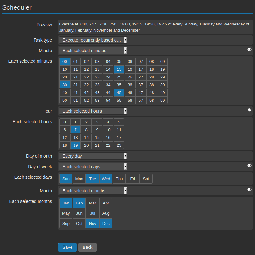
- Minute: On this field is possible to set the minute in the hour (between 00 and 59), when the action has to be executed. It’s also possible to set several minutes (even all minutes).
- Hour: On this field it’s possible to set the hour of the day, when the action has to be executed (between 0 and 23). Even in this case it’s possible to configure more options (even all hours).
- Day of month: On this field it’s possible to select the day of the month, when the action has to be executed (from 1 to 31). It’s possible to select more days even all.
- Day of week: Da questo campo sarà possibile programmare l’esecuzione dell’azione selezionando il giorno della settimana in cui deve essere eseguita. Anche in questo caso sarà possibile selezionare uno o più giorni (anche tutti).
- Month: The field Month allows to define in which month the action has to be executed; it allows to choose one or more months (even all).
For instance if we want an action to be executed every 15 minutes:
On the field Minute the numbers 00, 15, 30 e 45 must be selected.
If we want this action to be executed only between the 10:00 and the 11:00:
On the field Hour it must be set the number 10.
If the action must be executed only on Monday and the last day of the month (independently from the fact that it’s Monday or not):
On the field Day of month select the number 31, while on the field Day of week it must be selected the option Mon (Monday).
Eventually if the action has to be executed only on the first and the last month of the year:
On the field Month it has to be selected the option Jan (January) and Dec (December).
The field Preview offers the possibility to check when the WE111 will execute the action. According to our example the Preview will show the following:
Execute at 10:00, 10:15, 10:30, 10:45 if the day is 10 or is Monday of January and December
The action will then be executed every Monday and every end of Month of January and February at 10:00, 10:15, 10:30 and 10:45.
4.2. Execute every
The option Execute every allows to execute an action at regular interval of time. On the field Unit is possible to select the measurement unit among Seconds, Minutes, Hours and Days.
- Seconds Entering value “N” on the field Value, the action will be executed every “N” seconds.
- Minutes entering a value “N” on the field Value, the action will be executed every “N” minutes.
- Hours Entering a value “N” on the field Value, the action will be executed every “N” hours.
- Days Entering a value “N” on the field Value, the action will be executed every “N” days.
For instance, if a certain action has to be executed every hour:
On the field Unit select Hours.
On the field Value enter 1.
Also in this case the field Preview gives the possibility to check when the action will be executed. According to the above example, the Preview will show:
Execute every hour
The action will be then executed at the beginning of every hour.
4.3. Execute only once
The option Execute only once allows to enter the Scheduler in order to define when the action has to be executed.
Clicking on the icon  available at the right of the field Date, the scheduler is opened and it allows to define the hour, the day, the month and the year, when the action has to be executed.
Once executed the action, the event can be deleted, since it has to be executed only once.
available at the right of the field Date, the scheduler is opened and it allows to define the hour, the day, the month and the year, when the action has to be executed.
Once executed the action, the event can be deleted, since it has to be executed only once.
If, for example, it’s set to execute a certain action on the 31st of January 2023 at 12:30:00:
It’s required to scroll until the desired data, to select the day, complete the time fields and then click OK.
5. Variables monitoring
Beside the possibility of getting alarms notifications, it’s also possible to query the status of the created variables at any time.
The procedures for getting the status or value of a variable are the following:
- Page Status → Variables
- SMS, Chat and Email of Set/Get
- Customized commands, to be created defining an event type Incoming data
5.1. Variables status
The page Status → Variables collects and displays all created variables. The variables are visualized in alphabetical order and can be grouped at own discretion.
In order to create one or more groups of variables it’s required to go to page Configuration → Variables → Variables Groups:
Clicking on the tab New, a new page opens, where all created variables are available.
After digiting the name on the field Name, it’s possible to decide the order of visualization of the groups on the field Priority: the priority influences the groups order on the page Status → Variables, from 0 to 9, considering 0 he highest priority (i.e. the first group to be displayed) and 9 the lowest priority (i.e. this group will be the last to be displayed).
If two or more groups have the same priority, the alphabetical order will be respected.
Flagging the field Hidden, it’s possible to decide if the group and the variables will be shown on the page Status→Variables. Eventually it’s possible to choose the variables to be included in the group, selecting them from the list Available variables.
Once confirmed, clicking on Save, we will find the new created group on the page Status → Variables.
After the creation of the first group, all the variables not included in any group, will be automatically be included in the group Others.
Back to the page Status → Variables he situation will be as follows:
As you can see, on the right of the group name are two icons
- Cancel group: clicking on this icon, the group is deleted from the page. Nevertheless the group remains saved, and all associated variables will keep on working.
- Hide group: clicking on this icon, the group is reduced to the name, hiding all variables. Even in this case the functioning of the variables is not affected.
It’s possible to recall again the hidden groups and restore the reduced ones by clicking
Located on the bottom right of the page.
The variables chart is divided into 7 columns:
- Name: Variable’s name
- Value: Numerical or mnemonical value of the variable
- Unit: It shows the measurement unit assigned to the variable. For the variables with no measurement unit, this field remains void
- Set: It allows to set a value (or a status) on editable variables (DO and virtual). In case of DO variables, will be entered the defined status (for example “open” “closed”), that can be clicked to change the status of the variable. For the virtual variables it’s instead possible to enter a numeric value and confirm the setting by clicking set.
- Status: In case of DI and DO variables, a self explanatory icon will be shown: green
 or gray
  , according to the status and the configuration of the variable.
- Alarm: There’s a column, that reports the alarm status of a variable. The icon
 shows that no alarms are activated. The icon
  shows instead the presence of an event, configured as an alarm.
- Monitor: For al the variables that have a readable status, it’s possible to click on the icon available on the column Monitor, in order to visualize a realtime-graph on a new window of the browser:
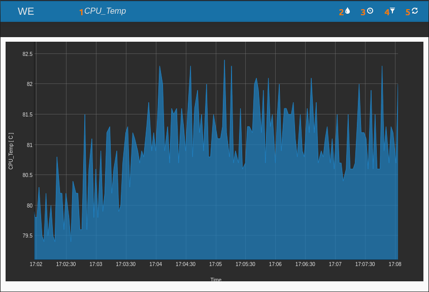
Moving your mouse pointer to any position of the graph, on the top right corner you’ll find displayed data, time and value of the variable at that specific point.
Beside the graph on the new window, the following elements will be available:
- 1: Name of the selected variable.
- 2: Icon for changing the colour of the graph area.
- 3: Icon for selecting the quantity of data to be displayed among: One minute (data referred to the last minute), One hour (last hour), One day (last 24 hours) and Full scale (by default, it shows all data available since the window has been opened).
- 4: Icon for choosing whether to apply any filter on data, to interpolate different points of the area.
- 5: Icon for restarting the data acquisition, but deleting the data previously collected.
The graph will be generated by reading in real time the value (or the status) of the selected variable, and by adding a new point every 2 seconds. The data will be added until the browser window remains open, without influencing the performance of the device (to this purpose will be used the resources of the PC in use).
More than one real-time graphs can be displayed at the same time: each one having a dedicated window.
The displayed data won’t be saved in the internal memory of the device, but will be lost at the closing of the window.
Note
The page Status → Variables, is automatically refreshed every 5 seconds. Thus it’s possible to read the status variations without refreshing manually the page.
5.2. Set/Get commands via SMS/Email/Chat
It’s possible to query or modify the status of variables by using a specific syntax via SMS, Chat or Email.
The fact that it’s possible to read or write a value, depends on the type of variable you’re interacting with.
5.2.1. Set
The variables where it’s possible to change the value through the command Set are the following: counter on digital inputs, digital outputs and virtual variables.
The command Set can be sent indiscriminately via SMS, Chat or Email. In all cases it’s necessary to define the parameters of the users, that will be allowed to send commands to the WE111 (telephone number for the SMS, name for the Chat, email address for the Email).
The users also have to be enabled to send commands, activating the relevant options on the configuration page of the users.
It’s also necessary to activate the SMS, Chat and/or Email (in this case it’s enough the service Incoming Email) services.
Once properly configured the WE111, it’s possible to use the syntax as reported below:
Command to be sent:
If we want to set the value “5” on virtual variable “Var1”, the SMS/Email or Chat message to be sent is:
Command to be sent:
In case it’s supposed to send an Email, it’s necessary to use the same syntax as above, entering the command on the subject of the same email.
If it’s required to set the values of more variables with one single command, it’s enough to separate the variables through a space:
Command to be sent:
Set Var1=5 Var2=10 Var3=15
It’s very important to respect carefully lower and upper cases.
Note
The commands must be sent respecting upper and lower cases, as defined during the configuration.
Note
To allow a user to send commands to the device, the relevant option has to be activated on the page modify/create users (see 7. Users).
Note
In case of emails, the command to be sent to the device must be included on the subject and not on the body of the email.
5.2.2. Get
All variables can be read, using the command Get.
The Get command can be used through SMS, Chat and Email. In all cases it’s necessary to define the parameters of the users, that will be allowed to send commands to the WE111 (telephone number for the SMS, name for the Chat, email address for the Email).
For authorizing the users to send commands, it’s necessary to enable the relevant functions on the user configuration page.
Also the SMS, Chat, and/or the Email service (both incoming and outgoing) must be enabled.
Once appropriately configured WE111, it’s possible to use the following syntax:
Command to be sent:
If we want to get the value of the virtual variable “Var1”, the SMS/Email or Chat message to be sent is:
Command to be sent:
In case it’s supposed to send an Email, it’s necessary to use the same syntax as above, entering the command on the subject of the same email.
If it’s required to get the values of more variables with one single command, it’s enough to separate the variables through a space:
Command to be sent:
It’s very important to respect carefully lower and upper cases.
Note
The commands must be sent respecting upper and lower cases, as defined during the configuration.
Note
To allow a user to send commands to the device, the relevant option has to be activated on the page modify/create users (see 7. Users).
Note
In case of emails, the command to be sent to the device must be included on the subject and not on the body of the email.
5.3. Customized commands
Using the function Incoming data t’s possible to create customized commands, both for setting the value of one or more variables and for create status messages.
In order to create a customized message to be sent as a text via SMS, Chat or Email, it’s necessary to define an event Incoming data (for further details see 3.1.2. Incoming data) and create some actions type Execute a command (see 3.2.4. Action Execute a Command).
Thus it’s possible to set the status of more variables.
On the other hand, in order to create a customized command suitable to report the value of one or more variables, it’s possible to use the character $:
Having created an event type Incoming data, and having then defined an action type Send Email, Send Chat, or Send SMS (see 3.2.2. Action Send SMS, 3.2.3. Action Send Chat and 3.2.1. Action Send Email), it’s possible to define the message, that WE111 will have to send to the configured users.
Inside the message it’s possible to enter the name of one or more variables preceded by $. At the message delivery, WE111 will substitute $VarName with the value of the variable itself.
6. Data delivery
The status of all variables can be delivered to a Portal or Web server, when properly configured.
The automatic delivery of the variables’ value can be very useful, when for instance it’s required to manage several machines/WE111 and to control the status of the main variables without connecting directly to the interface of each single device.
With the collected data it’s in fact possible to generate graphs and tabs, according to the desired setting of each portal.
Nethix Cloud is a very flexible and modular service, offered by Nethix and can be installed and configured, on request, on any third party platform.
If the user should decide to install the Portal on its own platform, Nethix offers documentation and support in order to integrate Nethix devices on the Portal.
Further information about Nethix Cloud service are available on the relevant on line documentation:
Portal.
Two steps are necessary, in order to let WE111 send the variables’ value:
- Enabling of the variables
- Configuration of the method and the destination of the sending
6.1. Enabling variables to data delivery
In order to send data to a portal, it’s first of all necessary to enable the variable/s to this purpose, by activating the option Cloud sending, from the page creation of a variable.
It’s possible to activate/deactivate the option of sending data to portal also from the page Configuration → Variables, by adding or deleting the flag on the column Cloud and clicking then Update.
6.2. Configuration of data delivery
After the selection of the variables to be enabled to data delivery, it’s necessary to configure all parameters, that allow the proper functioning of the system, at the page Configuration → Cloud
Some of the requested information on this page require a minimal know-how about data delivery technologies, or the support of the cloud provider.
On the first section General, some of the main settings have to be defined as for instance the service activation and the delivery frequency.
If the parameters required in this page are not defined, it’s not possible to proceed with the configuration.
- Variables sampling It enables/disables the delivery of variables value
- Sampling frequency It allows to set the time interval of the data sending
- Events sampling It allows to enable the sending of the events to a portal
Once enabled the service and set the interval of time, it’s possible to decide to enable one or more modalities and destinations among: HTTP, MQTT and Email report.
All deliveries to a portal/cloud executed by WE111 are then reported on the page Status → Services → Cloud.
Entering this page first of all it will be displayed the list of deliveries yet to be executed by the WE111.
At any time it’s possible to click on Refresh in order to update the information, or Empty box in order to delete all messages available in Outbox.
Clicking on the drop down menu on top of the tab, it’s possible to pass from Outbox to Sent.
In this last section are displayed some information about the already executed deliveries of the WE111:
At any time it’s possible to click on the tab Refresh in order to recall the information or Empty box in order to delete all messages available in Sent.
6.3. HTTP/S
From the tab HTTP it’s possible to enable the delivery to the Cloud offered by Nethix, or to any third party server.
Selecting Nethix API on the field Protocol, and enabling the delivery by flagging Enable, the delivery to the Portal nethix.co will be activated.
The Portal is a service offered by Nethix and grants the following options:
- To send data and get a summary of all plants.
- To visualize the detail of every single device and the logged data on a chart or tab.
- To create a synoptic, that allows to show the device’s status ina simplier and more intuitive way.
- To establish a remote access from the device to the portal, in order to be able to read and write the value of the variables, even in absence of a public IP address.
- To establish a VPN connection between a PC and a Portal. In this case, enabling the remote access, it’s possible to create a VPN network including all owned devices, avoiding any problems regarding non reachable IP addresses.
For further information, please refer to the documentation: Portal.
The default settings are:
The correct parameters are in any case indicated by Nethix at the activation of the service.
In alternative it’s possible to enable the data delivery to an external server. In this case it has to be selected the option HTTP on the field Protocol.
On General setup the following parameters have to be defined:
- Enable: Activate/deactivate the sending.
- User agent: The user agent that WE111 will use to authenticate at the server.
- Device ID: ID of the device (useful for managing more than one WE111 in the same server).
- Server Address: Address of the server for sending the data.
- Server address: Indirizzo del server a cui mandare i dati (completo di http://).
- Server port: Port of the server.
- Send mode: Modality of data sending. It’s possible to choose between POST and GET. Before activating the option, please refer to Nethix, for getting a sample string sent by WE111.
On Data delivery it’s possible to define the path inside the server, where the script for the received data processing is available:
- Script address: Name and complete path of the script inside the remote server.
- Manage portal response: WE111 waits for commands coming from the server, every time it has to execute a data delivery.
Note: In case of data delivery type Server, WE111 will use the same frequency as set for the sampling (Configuration → Cloud → General).
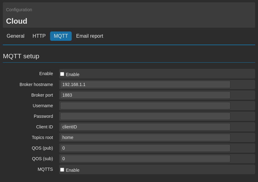
6.4. MQTT/S
On the tab MQTT it’s possible to configure the necessary parameters in order to let the WE111 communicate with any MQTT broker.
- Enable: Activate/deactivate the sending.
- Broker hostname: Server address where to send data.
- Broker port: Server port (default 1883).
- Username: Name of the user for authenticating at the server (if necessary).
- Password: Authentication password on server side (if necessary).
- Client ID: Reference ID for the Broker for identifying the WE111.
- Topics root: Main reference address, where the data will be saved.
- QOS (pub): Quality of Service in case the variable is with MQTT mode = Publish (default 0)
- QOS (sub): Quality of Service in case the variable is with MQTT mode = Subscribe (default 0). The QOS has range from 0 to 2, 0 the service grants the data delivery max. once (it’s not always sent), 1 the service grants the delivery of the data at least once (can be sent more than once), 2 the service grants that the data is entered correctly once.
- MQTTS: Enable/disable the use of TLS according to the server specifications.
The MQTT protocol offers two different modalities, that allow the device to communicate not only with a Web application, in order to show real time data, but possibly with other devices, not necessarily manufactured by Nethix.
The fact of putting in communication devices, that are deployed in different and distant plants, enhances the quantity of variables/signals that WE111 has to manage.
The two modalities of using the protocol MQTT are:
During the creation of a variable (see 2.1. Generic Settings) it’s possible to specify which one of the two modalities has to be used.
PUBLISH
If configured in Publish modality, at every changing of the variable value it will correspond a sending to the broker MQTT.
In this case the data delivery won’t respect the schedule specified at page Configuration → Cloud → General, but is executed immediately at every value changing.
A typical example may be the temperature value, which is read by the WE111 through the input.
At every changing of the temperature, the new value would be immediately sent to the broker, allowing anyone, who would be using the modality Subscribe (Nethix devices, third part devices, smartphone, tablet PC, and so on..) to visualize it.
This allows to make available a variable, read by the WE111 and other devices/users.
SUBSCRIBE
If configured in Subscribe modality, the information exchange with the Broker, occurs following the opposite procedure.
If a variable is configured according to this modality, the broker will notify to the device the status changing, and the WE111 will assign the new value to its internal variable.
A typical example of using this modality could be the temperature reading from a smart thermostat, MQTT compatible.
If a Virtual variable is defined, selecting the modality Subscribe, at every temperature changing the WE111 will assign a new value to its own variable.
This allows to define Events/Actions even on value/status of variables, read from other devices.
6.5. MQTT/S Report
From the tab MQTT it’s also possible to enable the MQTT report.
This function allows to send the variables status at regular interval of time, through the MQTT protocol and using the configuration parameters, indicated on the previous chapter.
The delivery of the variables and their values will be made in format JSON, which is easy to be interpreted on server side.
The first information reported will refer to data and hour of the report itself, and will be expressed following the Unix Timestamp format. The enabled variables and their relevant values will instead be entered later on.
MQTT report example:
{
   "Timestamp":"1650421200",
   "Temperature":"27.1",
   "Pressure":"1050",
   "Tank":"13.6",
   "Signal":"85",
}
In order to include a variable inside the MQTT report it’s enough to enable the option
Cloud sending (see
2.1. Generic Settings). It’s on the other hand not necessary to specify any
MQTT mode, that can be then left set on
Disabled.
The timing for generating and sending the report must be configured on page Configuration → Cloud → General.
6.6. Email report
From the tab Email report it’s possible to configure the delivery of the data collected by WE111 to one or more email addresses.
- Enable: Enable/disable the sending.
- Delivery time: Defines the time interval for sending the data to the enabled users. Please note, that the time of sampling (field Sampling frequency on tab General) and the time of sending may be different. It’s for example possible to sample a variable every minute and send the data only once a day.
To let the report be properly sent, it’s necessary to have correctly configured the email account associated to the WE111 (8.3. Email) and have enabled the option Receive report by email on the configuration of the users who are supposed to receive the email (7. Users).
The data will be included in the email as an attachment, according to the CSV format.
At the beginning of every line data and hour of data acquisition will be reported and the the variables with their values will follow. Every field is separated by others through the symbol “;”.
7. Users
In order to enter the Web Interface of the device and be able to get/send SMS, Chat and Email, it’s necessary to define the users.
There are three types of users: SYSTEM, ADMIN and USER. The main features of these three user levels are:
- SYSTEM
- Is able to visualize, edit, create and delete all other users.
- Is the only user able to create ADMIN users.
- Is the only user, that cannot be deleted (neither by himself). Logging in with the SYSTEM, user’s credentials it’s possible to modify any parameter (included username and password).
- Can access any function of the system.
- Can set an expiry date for all the users, after that date the users won’t be able to access the device and communicate with it (nevertheless the data won’t be deleted).
- ADMIN
- Can visualize, edit, create and delete USER users.
- Cannot delete himself, but can modify all parameters, including username and password.
- Can set an expiry date for the USER users, after that date the users won’t be able to access the device and communicate with it (nevertheless the data won’t be deleted).
- Can access any function of the system, as the SYSTEM user.
- USER
- Cannot visualize, edit, create nor delete any type of users.
- Can modify only his own parameters (but not delete himself).
- Can access exclusively the sub-menu Status, since it cannot edit the configuration of the system, nor create/edit/delete variables and events.
- The SYSTEM user and the ADMIN users can set an expiry date, after that date the USER user won’t be allowed to enter the device.
- Cannot reboot nor switch off the device.
At the start up is available the default System Administrator type SYSTEM, whose log-in credentials (to be changed as soon as possible) are the following:
Username: admin
Password: admin
7.1. Create a new user
To create a new user it’s necessary to go to the page Configuration → Users → Users.
In this page are displayed some information referred to the previously created users:
- Username It’s the username for the log-in.
- Full name The complete name assigned to the user.
- Privileges It’s the level assigned to the user (SYSTEM, ADMIN or USER).
- Expire date It’s the expiry date for the user, after that date the user will be disabled (but not deleted).
From the column Delete it’s possible to select one or more users to be deleted by clicking on the tab Delete selected users.
To edit a previously created user just click on his username, in order to create a new one, just click on the tab Add new user.
The following are the parameters to be set, in order to create a user:
- Username The username used for the log- in. No empty spaces nor special characters are allowed (apart from “_”). It’s case sensitive: it’s recommended to pay attention to the use of lower and upper case.
- Password The password to be used for the log-in (to be entered twice). The password can be composed of alphanumeric and special characters. It’s also case sensitive: it’s therefore recommended to pay attention to the use of the lower and upper case.
- Full name The complete name assigned to the user. Once executed the log-in, the Full name will be reported on the top left corner, near the name assigned to the WE111. Clicking on it, the page for the user configuration will be entered.
- Privileges The level to be assigned to the client, among SYSTEM, ADMIN and USER (see 7. Users).
- Expire date It allows to define a date, after which the user won’t be able to enter the interface nor send/receive any command and notification from and to the WE111. If it’s not intended to set an expiry date for the user, the field remains void.
- Phone number The telephone number associated to the user. It’s necessary if the user wants to send/get SMS to/from the device, on the contrary it’s allowed to leave the field void. Remind that the telephone number must be entered complete with country code, in the format +nn (+39 for example for Italian numbers).
- Email address The email address associated to the user. It’s necessary if the user wants to send/get Emails to/from the device, on the contrary it’s allowed to leave the field void.
- Chat name The name used in the chat and the name of the chat server associated to the user (e.g. @john:server.chat). It’s necessary if the user wants to send/get chat messages to/from the device, on the contrary it’s allowed to leave the field void.
- Actions In this section it’s possible to enable/disable several options connected to the user:
- Receive alarms by SMS If enabled, it allows the user to receive alarms via SMS from the WE111, if previously configured.
- Receive alarms by email If enabled, it allows the user to receive alarms via email from the WE111, if previously configured.
- Receive report by email If enabled, it allows the user to receive email reports from the device, according to the preconfigured settings. (6.6. Email report).
- Send commands by SMS If enabled, it allows the user to send commands to WE111 via SMS.
- Send commands by email If enabled, it allows the user to send commands to WE111 via email.
- Send commands by chat If enabled, it allows the user to send commands to WE111 via chat.
- Receive remote command If enabled in case of emails sent by WE111 to the user won’t show on the subject the name assigned to the device. This allows to send Set/Get commands between devices (5.2. Set/Get commands via SMS/Email/Chat).
7.2. Groups of users
If several users are available in the system, the management of events and actions may be complicated.
In order to simplify the situation, it’s possible to define and create groups of users.
In the events definition, when it’s time to configure the users that will receive the notifications via SMS, Email or Chat, it’s possible to select a previously created group of users, instead of choosing each single user.
This allows to have a higher flexibility, because for example, if a user should be added or removed from the list of the users enabled to receive notifications from the device, it would be enough to edit the group of users instead of modifying all events previously created.
In order to create, delete and edit the groups of users, it’s necessary to go to page Configuration → Users → Groups.
On this page are available some information about the previously created groups, as:
- Group name The name assigned to the group.
- Description The description of the group.
- Users The number of users available in the group.
From the column Delete it’s instead possible to select one or more groups to be deleted by clicking Delete selected groups.
To edit an existing group, click on the name of the desired group. On the other hand, to create a new group, click on Add new group.
In order to correctly create a new group only few information are necessary:
- Group name The name to be assigned to the group.
- Description The description of the group.
- Users This field allows to select the users, that take part to this group. After selecting them with the mouse from the box Available Users, it’s enough to click > to send them inside the box Selected users or < to delete them from the group.
Clicking on Save the group will be created.
Here are some comments regarding the groups of users:
- A user may not belong to any group.
- A user may belong to more than one group (even to all groups)
- WE111 can identify repeated numbers, email addresses or chat names. If a user is available in several groups, in case of alarms he will receive the alarm just once.
- If a group is deleted, the users inside that groups won’t be deleted.
8. Connectivity
A very important role in the settings, in order to have a perfectly functioning system, is the connectivity, i.e. all the channels available for communicating with the device.
All the settings regarding the network interface, the service and connectivity functions of the device are available under the section Networking of the Menu.
8.1. Network interfaces
Clicking on Networking → Interfaces we enter the section, where it’s possible to define the modality for WE111 to enter into the internet network.
In case of WE111 the only option is Modem.
8.1.1. Data connection and SMS
WE111 allows to establish a GPRS/LTE connection in order to remotely access the Web interface of the device and send data, chat messages or email.
Selecting the option Networking → Interfaces → Modem it’s possible to set some important parameters for the correct functioning of the data connection, given by the SIM card, available on the device.
DATA CONNECTION
On the section Connection mode it’s possible to enable the service and specify, if the connection has to be on demand or always on:
- Always On WE111 will keep the connection always active. If it should fail (insufficient credit, low signal etc..), it will be restored as soon as possible.
- On demand the connection will be activated only on request of a registered user, through the sending of a Wakeup (9. System commands) message and will have a duration of 15 minutes, before the connection fails again. If services that require a connection (data delivery, email delivery, chat and so on..) will be active, WE111 will establish a temporary connection, that will automatically terminate after the operations have been executed.
If everything has been properly configured, after few minutes the connection GPRS/LTE will be activated. On the status panel, positioned on the right side of the web interface, the GPRS/LTE indicator will become green, below the connection uptime and the relevant IP address will be shown.
It’s possible to enter some advanced parameters clicking on Advanced:
- Ping enable If enabled, it allows the device to execute some pings at regular interval of time to the addresses, specified on the fields Keepalive server. This allows the system to identify possible critical issues and to restore as soon as possible the connection. The activation of this option increases the control over the connection status, but increases also the use of SIM data.
- Keepalive server 1 In this field it’s possible to specify the primary address where the device will try to send the ping to, in case the Ping enable option is active.
- Keepalive server 2 In this field it’s possible to specify a second address, in case that the primary shouldn’t be available.
- Address/Control compression It enables/disables the compression of the fields address/control during the negotiation. Except particular cases, it’s recommended not to modify the default settings (enabled).
To make sure that the GPRS/LTE connection is successfully established, it’s important that the following operations have been executed:
- Provide WE111 with a SIM (rechargeable or on contract) enabled to data traffic.
- Enter the APN on the field APN for the operators that require that.
- Screw the antenna and make sure that the GSM coverage is enough.
- Enable the service GPRS/LTE through the field Enable.
It’s possible to check the quality of the connection using the diagnostic tool
Ping (
10.3. Ping).
From the section SIM configuration some parameters can be set, that are fundamental for a correct functioning of the SMS service, and of the GPRS/LTE connection, according to the specifications of the selected provider.
- APN The APN is the name of the access point of the GPRS/LTE network. It changes according to the operator and to the contract (in some cases this may not be necessary). It’s an important parameter for a correct functioning of the connection. In case this should not be known, it’s required to contact the provider.
- Username It’s the name of the user to be used for the GPRS/LTE connection. Except particular cases required by the provider, this field must be void.
- Password It’s the password to be used for the GPRS/LTE connection. Except particular cases required by the provider, this field must be void.
- SIM number Telephone number of the SIM inserted in the device. It’s not relevant for the functioning of the device (it’s never used by the WE111).
- SMS center Provider’s SMS service center. With some SIMs may not be necessary. In case this should not be known, it’s required to contact the provider.
SMS Service
On the section SMS configuration, it’s possible to enable/disable the SMS service (on the field Enable SMS) and choose whether to enable or not the sending of possible SMS notifications as previously configured (on the field Send events) (3. Events/Actions).
Once activated the SMS service, it’s possible to test it through the section SMS test: entering a valid telephone number preceded by the country code (for instance +39NNNNNNNN in case of an Italian number), WE111 will try to send an SMS having the following text ” Test message from WE111 “.
To make sure that the SMS service is working properly, and lets the users communicate with WE111 and the device send possible alarms notifications, it’s necessary to follow carefully these steps:
- Set the SMS service centre on the field SMS center.
- Enable the SMS service on the field Enable SMS.
- Enable the SMS sending on event (field Send events).
- Define at least one user and make sure that the options for the receiving/sending SMS are activated (7. Users) and that at least one valid telephone number is available.
- Create one or more events having Send SMS as action (see 3. Events/Actions).
- Check your SIM card balance
- Make sure that the SIM has no PIN code.
- Make sure that the antenna is correctly mounted and the signal is enough.
All sent and received SMS can be displayed on the page Status → Services → SMS.
At the access, the first page to be displayed is the one containing the SMS received by the device
On the displayed tab, the following information will be shown:
- Number The number of the message sender.
- Reception date In this field are reported the data and time when the WE111 has received the message.
- Text The field where the text of the received message is shown.
At any time it’s possible to click on the tab Refresh in order to update the information, or Empty box in order to delete all messages available inside Inbox.
Clicking on the drop-down menu on top of the tab, it’s possible to pass from Inbox to Outbox.
From this tab it’s possible to visualize all outgoing messages of WE111.
The visualized information are:
- Number The number of the message receiver.
- Creation date In this field are reported the data and time when the message has been created.
- Text The field where the text of the message is shown.
At any time it’s possible to click on the tab Refresh in order to update the information, or Empty box in order to delete all messages available inside Outbox (i.e. messages that won’t be sent by WE111).
Clicking on the drop-down menu on top of the tab, it’s possible to pass from Outbox to Sent.
In this last tab are displayed some information regarding the SMS already sent by WE111.:
- Number The number of the message receiver.
- Send date In this field is reported the data and time when WE110 has sent the message.
- Text The field where the text of the message is shown.
At any time it’s possible to click on the tab Refresh in order to update the information, or Empty box in order to delete all messages available inside Sent.
8.2. Activable services
The section Networking→Services of the menu allows to enable some additional services, that will use the connectivity of the device:
8.3. Email
Before proceeding with the configuration of the WE111, it’s necessary to do the following:
- After having defined the Provider (Gmail, Yahoo or any other..), enter its site and create a new valid email account
- On the provider’s site get informed about the parameters to be entered, in order to have a correct configuration of the mail.
Once created a new email account, it’s possible to pass to the configuration of WE111, defining whether to enable the outgoing emails, the incoming or both of them in th epage Networking→Services→Email.
The necessary parameters for the email sending from WE111 have to be defined on the section Outgoing mail setup:
- Enable outgoing mail service It enables/disables the mail services.
- Server type It allows to specify the type of mail server (currently it’s available only the option SMTP).
- Server address It’s the address of the mail server (for example smtp.gmail.com).
- Port It’s the port number to access (for instance 587).
- Email address It’s the email address associated to the WE111. This will be the address visualized by the users, who will receive emails from the device.
- Username Username of the mail account associated to WE111.
- Password Password of the mail account associated to the WE111.
- SSL-TLS Encryption.
Once clicked on Save, on the bottom of the page a new section called Outgoing mail test will appear: from this section it’s possible to send a test email to any address.
On the section Incoming mail setup it’s possible to define the necessary parameters for the reception of the emails sent by the enabled users:
- Enable incoming mail service It enables/disables the mail reception service.
- Server type It allows to select the type of mail server (currently available only POP).
- Server address The address of the mail server (for example pop.gmail.com).
- Port Number of the access port (for example 995).
- Email address The email address associated to the WE111. This is the address visualized by the users, who will receive emails form the device.
- Username Username of the mail account associated to the WE111.
- Password Password of the mail account associated to the WE111.
- SSL-TLS Encryption.
A properly configured mail service will allow the WE111 to send notification mails to the configured users (see 3.2.1. Action Send Email), to receive commands from registered users (see 5.2. Set/Get commands via SMS/Email/Chat and 9. System commands), to send/receive commands to/from other devices and to send scheduled reports (see 6.6. Email report).
All sent and received emails can be visualized on the page Status → Services → Email.
At the access, the first page shows the emails received by the device
On the displayed tab, following information are shown:
- Mail address It shows the sender of the mail.
- Reception date It shows the date and time of the email receipt.
- Text This field shows the text of the received email.
Any time it’s possible to click the tab Refresh, in order to refresh all information, or Empty box in order to delete all messages available inside Inbox.
Clicking on the drop-down menu on top of the tab, it’s possible to pass from Inbox to Outbox.
On this tab it’s possible to visualize all emails not yet delivered by WE111.
The displayed information are the following:
- Mail address It shows the email receiver.
- Creation date It shows the date and time of email creation.
- Attempts Delivery attempts made by WE111.
- Text This field shows the text of the email.
Any time it’s possible to click the tab Refresh, in order to refresh all information, or Empty box in order to delete all emails available inside Outbox (i.e. messages that will never be sent by WE111).
Clicking on the drop-down menu on top of the tab, it’s possible to pass from Outbox to Sent.
In this last tab are displayed some information regarding the mails already sent by WE111:
- Mail address It shows the receiver of the email receiver.
- Creation date It shows the date and time of email creation.
- Attempts Delivery attempts made by WE111.
- Text This field shows the text of the email.
Any time it’s possible to click the tab Refresh, in order to refresh all information, or Empty box in order to delete all emails available inside Sent.
8.4. Chat
WE111 is able to use the communication standard Matrix (
matrix.org), which is a free standard suitable for the communication via internet, with the peculiarity of being decentralized.
The functioning is the same as in all other common chat systems, i.e. it allows to communicate with the device through an instant messaging service, thus being a valid alternative to the use of SMS and emails.
The main precondition for a successful operating of the chat service, is that the device can connect to the internet network.
WE111 already has its own client necessary for the communication via chat, on the other hand a user can choose one of the clients among the many available (by choosing directly on the official page of the standard
matrix).
There are also cross-platform clients, i.e that can be installed on any PC/smartphone/tablet, as well as clients that can be used directly on any common browser and do not require the installation of any additional software.
An example of cross-platform client, extensively tested with our devices is
Element (
element.io), available on iOS, macOS, Android, Windows and Linux.
Expert users, that might want to integrate the Matrix standard on their own platforms/servers, can have at their disposal some bridges, that will allow the inter-operability with other instant messaging services as for instance Whatsapp, Telegram, iMessage and many others.
Being a third party standard, Nethix cannot give support for integrating Matrix with the platform/server of the customer.
Before proceeding with the configuration of the chat service inside the WE111, it’s necessary to create a new chat user to be associated to the device.
Choosing for example to use
Element (highly recommended), the new user can be created from the dedicated web page
app.element.io.
Once checked that the device is able to connect to the net and having created a chat user to be associated to the WE111, it’s then possible to proceed with the configuration of the service from the page Networking → Services → Chat.
On the section Chat service setup must be defined the necessary parameters for the successful functioning of the service:
- Chat enable It enables/disable the chat service.
- Chat server It allows to define the chat server, that WE111 shall connect to (for example matrix.org).
- Room name It’s the name of the chat room (for example Home).
- Device username The name of the chat user to be associated to the WE111. The device will send and receive messages using this name.
- Device password The user password to be associated to the WE111.
- Sync timeout Timeout in seconds referred to the synchronization with the server.
Once clicked on Save, at the bottom of the page a new section called Chat test will appear; from that section it’s possible to send a test message via chat to the chat room of the device.
All by the device sent and received chat messages can be visualized on the page Status → Services → Chat.
At the access, on the first visualized page will show the messages received by the device via chat.
On the displayed tab the following information are available:
- Sender It shows the sender of the messages.
- Reception date It shows the date and time when the WE111 has received the message.
- Text This field shows the text of the received message.
Any time it’s possible to click the tab Refresh, in order to refresh all information, or Empty box in order to delete all emails available inside Inbox.
Clicking on the drop-down menu on top of the tab, it’s possible to pass from Inbox to Outbox.
On this tab is possible to visualize all not yet delivered messages of the chat.
The available information are the following:
- Creation date It shows the date and time of message creation.
- Text This field shows the text of the message.
Any time it’s possible to click the tab Refresh, in order to refresh all information, or Empty box in order to delete all messages available inside Outbox (i.e. messages that will never be sent by WE111).
Clicking on the drop-down menu on top of the tab, it’s possible to pass from Outbox to Sent.
In this last tab are shown some information about the already sent messages:
- Send date In this field are visualized date and time, when WE111 has delivered the message.
- Text This field shows the text of the email.
Any time it’s possible to click the tab Refresh, in order to refresh all information, or Empty box in order to delete all messages available inside Sent.
Using the structure of the chat room (which is quite similar to the groups used by all common instant messaging apps) it’s possible to organize in groups a high number of devices and users.
Several devices can in fact be included in the same chat room and be able to communicate each other.
Anybody, having a Matrix account, can be added to any chat room, and will be allowed to receive all messages sent by the other devices of the same chat room (beside the messages sent by the other available users).
In order to manage the device through the chat service, it’s necessary to register the user inside the WE111 in the relevant section:
7.1. Create a new user.
On the field Chat name must be entered the username associated to the user, according to the following format:
@my_username:matrix.org
where of course instead of my_username it must be entered the correct name.
Eventually must be enabled the option Send commands by chat.
8.5. VPN
WE111 is compatible with Open VPN standard, that allows to connect with a high number of VPN servers and be easily integrated on the VPN of the client.
The VPN service supplied by Nethix through the platform Nethix Cloud uses the same standard.
From the page Networking → Services → VPN is possible to enable the VPN service towards Nethix Portal or any another server.
There are two possible modalities to enable the VPN:
The automatic VPN is used to establish a secure connection with Nethix Cloud Portal. Moreover it allows to establish a secure and encrypted connection between a PC and a device.
Choosing this option, no particular operations are required by the user, since the necessary parameters are already pre-set in the device:
To let a PC connect with Nethix VPN, in order to reach and connect to the required WE111, the following procedures are available:
- Client OpenVPN: Download the Open VPN client from the official page of the Standard (further information are available here).
- QuickTunnel: Download the free Software Quicktunnel, created by Nethix and compatible with Windows, macOS and Linux (further information available on relevant manual QuickTunnel).
- Manual
The manual VPN is used to establish a secure connection to any other server VPN, compatible with the Standard OpenVPN.
The parameters to be configured in order to enable a manual VPN are the following:
- VPN mode: in this case the modality is Manual.
- VPN configuration: it’s a configuration file released by the VPN Server provider. The files shall contain also the certificates, according to the Open VPN Standard.
- VPN Service user: the user name used by the WE111 to authenticate in the selected VPN server.
- VPN Service password: the password associated with the username.
Note
The VPN connection can significantly affect the SIM data traffic.
8.6. DDNS
WE111 offers also the possibility to associate its own connection with a dynamic DNS service, choosing one of the available providers from the list on page Networking → Services → DDNS.
- Provider: On this field it’s possible to choose the Provider’s.
- Hostname: The device, once properly configured, will answer to this address (after the creation of an account on the site of the selected Provider).
- Username: Username associated with the account, created from the site of the Provider’s.
- Password: Password associated with the username.
This service allows the remote access to the WE111 even without a static IP. At every new connection, the device will authenticate at the Provider using above mentioned parameters and indicating its own IP address.
In order to reach the Web Interface of the WE111 it’s enough to enter the hostname associated with the device on the browser.
For further information get in touch with the selected Provider or with Nethix support.
Note
The DDNS service allows to access the device without knowing the correct IP address (which may vary at every new connection). It’s nevertheless necessary to have a public IP address for the correct functioning of the connection.
10. Diagnostic
WE111 offers some diagnostic operations and allows to visualize some information about the system functioning.
Entering the section Diagnostics it’s possible to receive some additional information about the active connections, in order to check the functioning.
10.1. System logs
From the page Diagnostics → Logs → System it’s possible to read the last 20 logs of the system.
On the reported tab are displayed some useful information for getting a report about the system status and identify possible errors.
To update the list of the logs, click on Refresh.
In case of error notifications, double check the configuration of the device and revert to Nethix support service.
On the page Diagnostics → Logs → Boot it’s possible to read the system boot logs, i.e. all operations that are executed by WE111 at every start/reboot.
Such information can be interesting for Nethix Support service, in case of assistance.
10.3. Ping
In case of failures in the communication, as for instance during the data delivery to a Portal, mail or any other operation, WE111 gives the possibility to execute a ping towards any host, allowing to select the network interface to be used.
For this operation, enter the page Diagnostics → Ping.
- Host Enter in this field a valid Hostname, to be reached through the ping (for example www.google.com).
- Interface Network interface to be used for reaching the defined host. According to the configuration of the device or of the active services, it’s possible to choose between 4G and VPN.
- Count It allows to set the number of ping to be executed.
Once filled in above mentioned fields, clicking on Ping, the operation starts. The results will be reported on the area below, letting the user detect possible malfunctions.
11. System operations
11.2. Configuration overview
WE111 allows to have a complete overview of the configuration made by the user, and it’s accessible in one single page in order to simplify the review of the entered information.
Entering the page Configuration → Overview is available a complete summary of the configuration made, divided into the following sections:
- Variables The list of the created variables, divided into variables groups; here it’s possible to get some fundamental information regarding their configuration. The variables, that are not associated with any group, will be displayed under No group
- Events Here are reported all events and relevant actions, associated with the links, that allow to detect immediately the connected variables and the users, that are the recipients of the actions
- Users Here is the list of users groups. Each group contains additional information regarding the users, that are part of the group. The users that are not included in any group, are displayed under No group
On the right of every position, displayed on the configuration Overview is the icon  that allows to expand the contents and access to further details.
11.3. System settings
On the section Configuration → General Setup some general device settings can be defined and some additional services can be activated.
11.3.2. Date and time
On the page Configuration → General Setup → System, under the section Time/Date, it’s possible to set the date and time of the device:
- Installation time/date It allows to specify the date and time when the plant has been installed. The purpose of this information is to identify the device, and has no influence on the functioning.
- Set time/date It allows to set manually the date and time of the device, if the option Enable NTP is disabled.
- Enable NTP It enables the service for the automatic synchronization of the time. Once a day, at every start and reboot, WE111 connects to a server, in order to get the precise and updated date and time, according to its own timezone.
- Select timezone It allows to set the timezone.
It’s also possible to specify a different NTP server as the default one, by clicking the link Advanced.
11.3.3. Web interface personalization
Some graphical customizations of the device Web Interface are possible; these are available for all the users on the page Configuration → General Setup → Web Interface.
On the section Web interface theme theme it’s possible to select the device look and feel among Dark (dark version) and Light (light version).
On the section Web interface customization it’s possible to modify some other elements of the device:
- Logo It allows to select an image to be used as Logo, replacing Nethix logo on the top left corner.
- Prevalent color The primary colour of the page (RGB hexadecimals colour e.g.: #00BC5).
- Font color Colour of the text (RGB colour hexadecimals e.g.: #00BC5).
- White icons Disabling this option, the icons of the header (help, poweroff, reboot, logout) will be displayed in black colour.
- Background color It’s the colour of the page background (RGB hexadecimals colour e.g.: #00BC5).
- Footer It allows to configure the footer at will (it’s allowed the use of HTML code).
Every field, that allows a colour, if clicked, will show a colour picker, that will allow an easy selection of the desired colour, and will set automatically the correspondent hex value.
11.5. Configuration Backup/Restore
WE111 offers the possibility to make a backup of the configuration made on the device in the form of an encrypted file, on the page System → Backup/Restore.
The backup includes:
- Created variables
- Associated events and actions
- Networking settings
- Created users
- Services enabling and configuration
On the other hand, these won’t be included in the back up:
- System log
- Service log
- SMS/Chat/Email/Cloud Archives
To execute the backup, click on Backup on the section Download configuration.
Once received the encrypted backup file, it’s possible to upload it on any other device, having the same hardware and software as the original one.
From the section Restore configuration, simply select the backup file and click Restore. At the end of the operation, it’s recommended to reboot the device to make the changes effective.
The Backup/restore tool can be useful also in the case, that a configuration copy should be kept as reference for future upload on the original device or for installing the same configuration in several devices.
In this last situation, i.e. to make a Restore on a different WE111 as the original one, where the back up has been created, it’s very important to know the following:
- To transfer the configuration of a WE111 to another, it’s necessary that both devices have the same version. Differently please contact Nethix support.
11.6. Logs reset
The internal memory of WE111 allows to log a high quantity of data. Nevertheless, to avoid the overload of the device, it’s possible to delete any available log from the page System → Reset Logs.
The logs that can be deleted are:
- Chat Delete all received and sent chat messages.
- Email Delete all emails available in the memory: sent, received and outgoing.
- Portal Delete all data deliveries sent to an external portal.
- Commands Delete all logs, referred to execute a command (not viewable on the Web Interface).
- SMS Delete all SMS available in the memory: sent, received and outgoing.
- 4G Delete all logs referred to the internal modem connection (not viewable on the Web Interface).
- Events Delete all logs referred to the events/actions so far occurred.
Once selected one or more positions, just click on Erase logs to delete the logs permanently from the device memory.
11.7. Factory reset
In case it should be necessary to reset the device to the factory settings, and thus delete all logged data and the configuration previously made, it’s possible to make it on the page System → Factory Reset.
After clicking on the only available tab in the page, it’s necessary to confirm the operation before proceeding.
Once confirmed, the WE111 will reboot and be again available via USB.
Note
The factory Reset deletes all settings, including also those referred to the connectivity. It’s therefore suggested to avoid a remote execution of this operation.
11.8. Device upgrade
WE111 can be upgraded any time on client’s request or on notification by Nethix.
The upgrades can be made according to 2 different procedures: writing the name of the required version and downloading it from the official Nethix server (after having contacted Nethix Support Service), or in alternative uploading on the device the encrypted file, containing the upgrade (to be requested at Nethix Support Service).
Both procedures are available on page System → Ugprade.
On the section Upgrade from official server it’s possible to enter the name and the number of the required version, to be downloaded directly from Nethix Server.
In order to identify the right version to be installed and get the name and number of the version to be uploaded, it’s necessary to contact Nethix Support Service.
Once received the right string, it must be entered on the field Version. Click then on Upgrade.
The download time depends on the active connection speed on the WE111. Once downloaded the required version, WE111 reboots and then install it. This operation may require about three minutes.
When WE111 is on line again, it’s suggested to enter the interface and check if the upgrade has been successfully executed (it’s enough to check it on the status panel).
On the other hand, from the section Upgrade from file it’s possible to send to the WE111 an encrypted file containing the upgrade, after having downloaded it on the PC.
The file depends on the previous version available on the device and must be required at Nethix Support Service.
To execute the upgrade it’s required to select the file to be sent and then click on Upgrade.
Once sent the file to the device, WE111 will reboot and install the new version.
The download time depends on the active connection speed on the WE111. Once downloaded the required version, WE111 reboots and then install it. This operation may require about three minutes.
When WE111 is on line again, it’s suggested to enter the interface and check if the upgrade has been successfully executed (it’s enough to check it on the status panel).
11.9. Features
The device features are some hardware and software optional functions that compose the system.
To check the enabled options on the device, go to page System → Features.
Clicking on the eye-shaped icon positioned near the section Supported features it’s possible to display the complete list of enabled features.
On the section Update from file it’s possible to select an upgrade file that, combined with a security code, will allow at any time to add or delete the required features.
Both file and code must be required from Nethix Support Service and refer to a single WE111 device. It’s not possible to upload on a WE111 the file created for another WE111.
If it’s intended to use the backup/restore function on two devices, it must be checked that both of them have the same list of enabled features.
11.10. Plugins
The plugins are a set of encrypted files that allow to add or change a part of the configuration and of the available web pages.
To upload a plugin or the check the list of the currently installed plugins on a device, enter the page System → Plugins.
This interesting tool allows for instance to send a file to the WE111, in order to add a pre-set configuration according to the specifications or the requirements of the customer.
Through a plugin it’s possible to add:
- Variables
- Formulas
- Events and actions
- Customized pages or dedicated to a specific application
The main difference between loading a plugin or make a restore from a device backup , is that through the plugins some new dedicated pages can be added, and some variables, events, actions can be added to the already available (while with the restore procedure the existing configuration is simply overwritten).
For a deeper information about the available plugins or to request a customized plugin, it’s necessary to contact Nethix Support Service.
13. Warranty and support
Nethix warrants to the buyer that the product will be defect-free within two years (24 months) from the date of purchase.
During warranty time, and against presentation of purchase invoice, the product will be repaired or replaced, at Nethix’s discretion, without any additional costs as regards spare parts and repair, if the damages are proven to be manufacturing defects.
Warranty will be voided if the product has not been used properly.
In case of technical problems the user can ask for support:
14. Return and repair
Product return to NETHIX must be previously authorized, requesting a RMA number.
Please send an Email at Nethix containing all following information:
- Complete customer’s name and address
- Distributor’s or Reseller’s name and address
- Date of purchase
- Product P/N and S/N as displayed on the product or the package
- Detailed description of fault and/or reason for return
Nethix will communicate the RMA number, in order to start the return procedure of the product.
The delivery of the goods shall be arranged DDP at Nethix premises.
Products returned without factory seals will be automatically treated as out-of-warranty repair services.

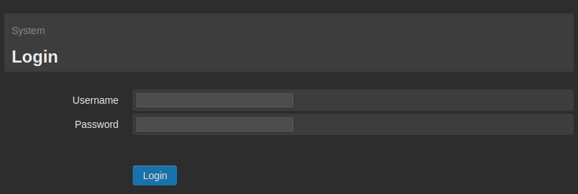
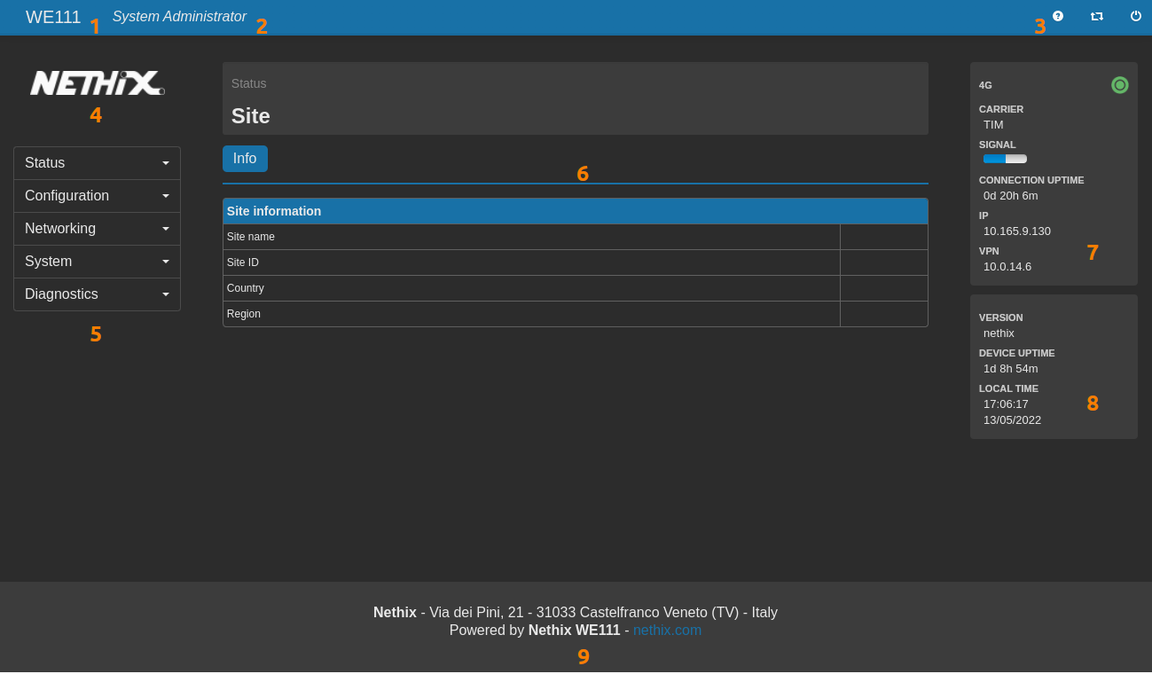
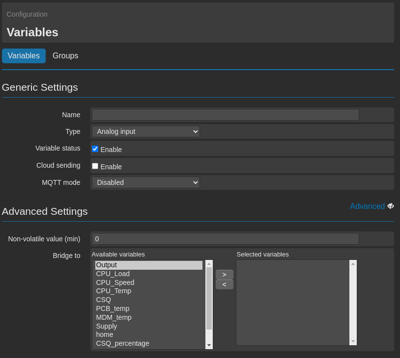
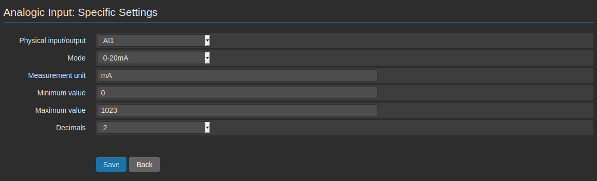
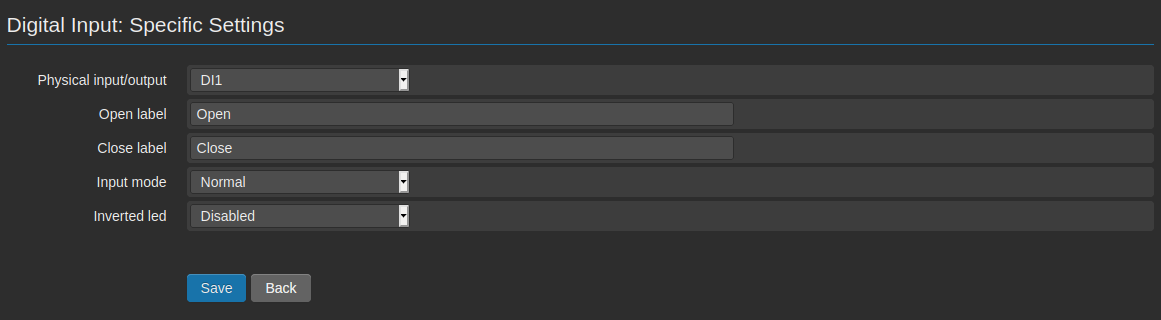
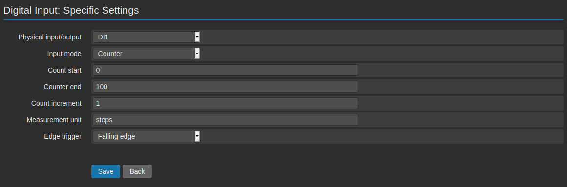
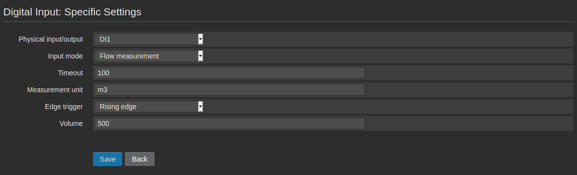
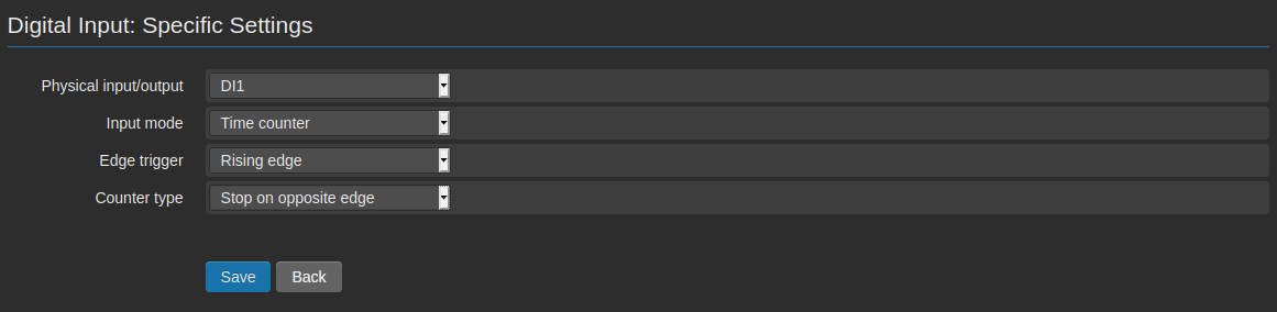
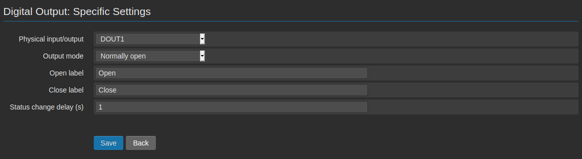
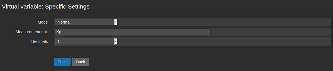
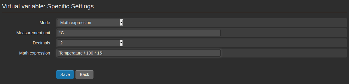
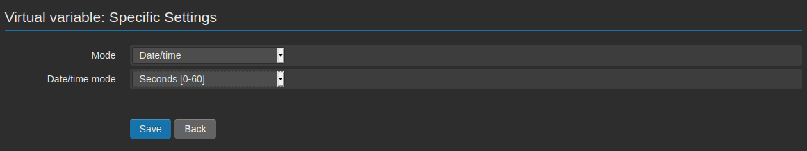
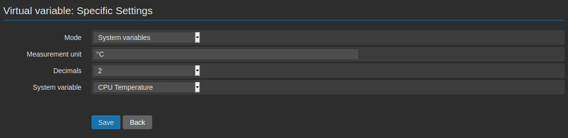
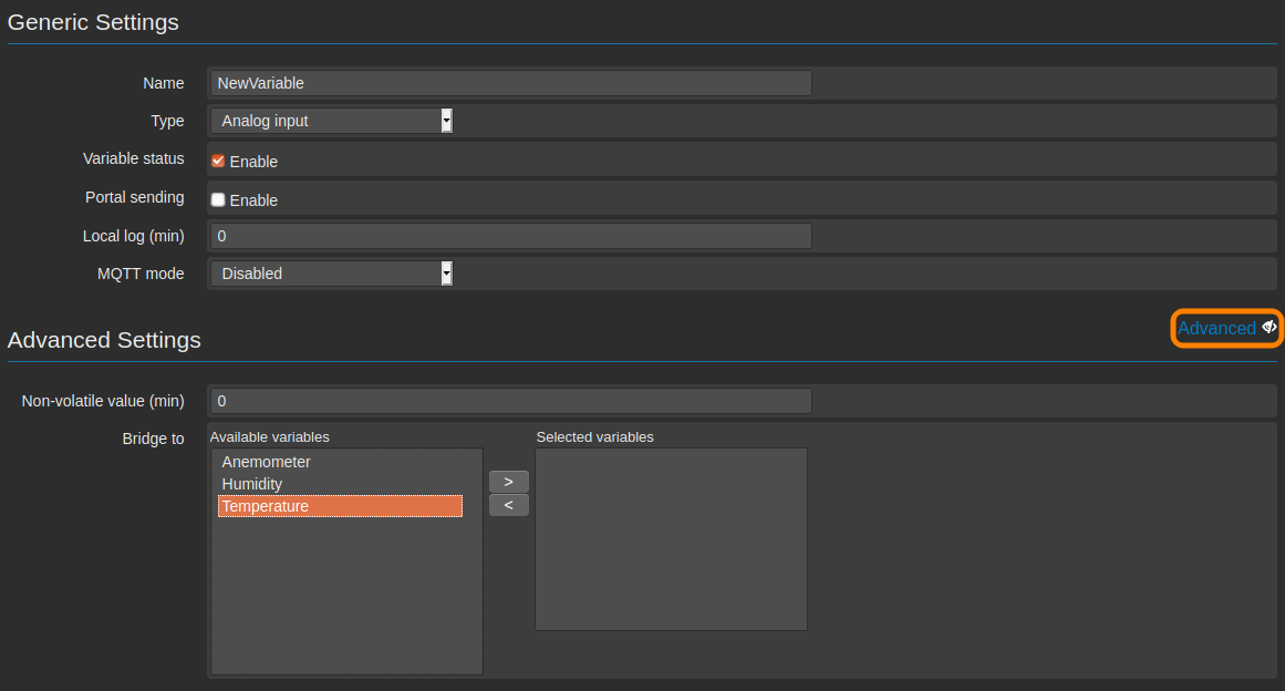
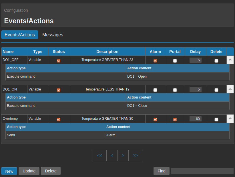
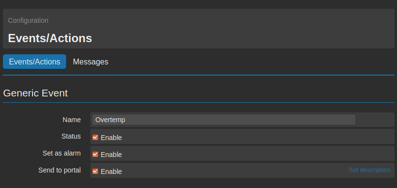
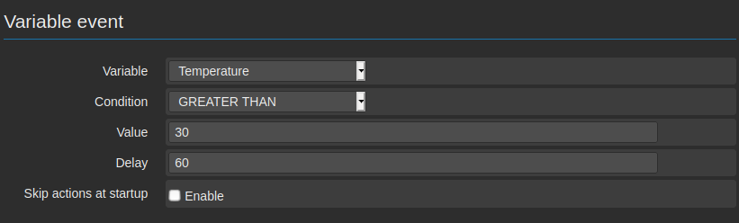
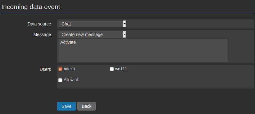
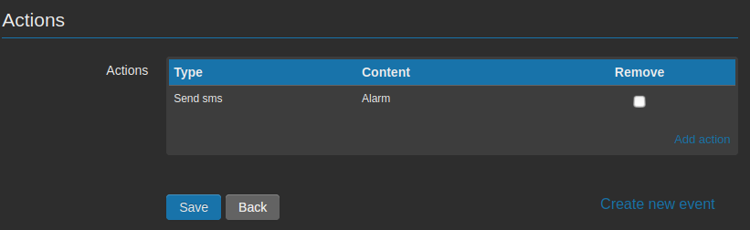
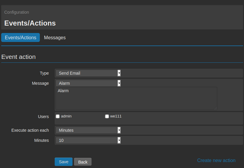
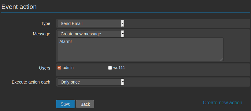
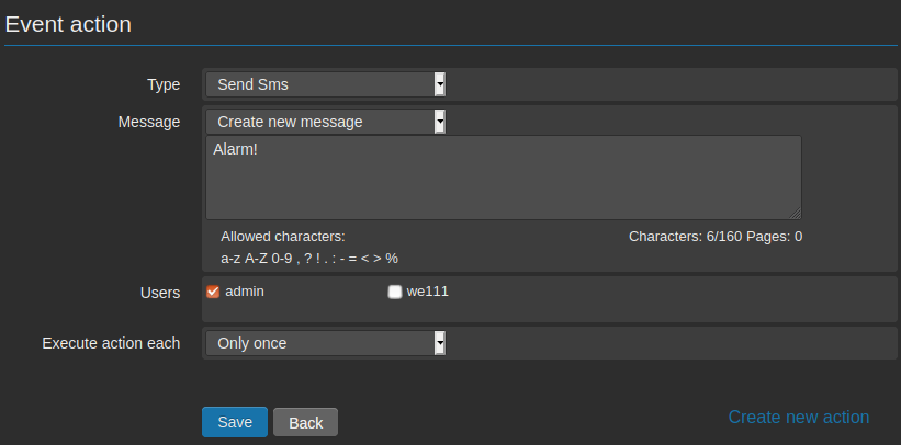
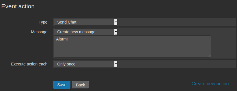
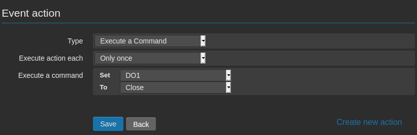
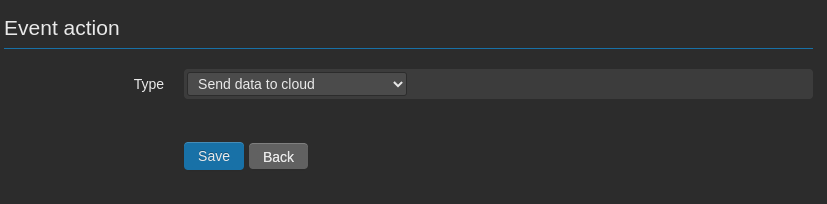
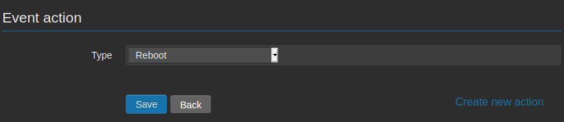
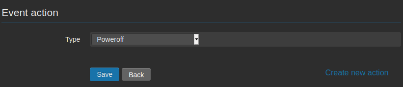
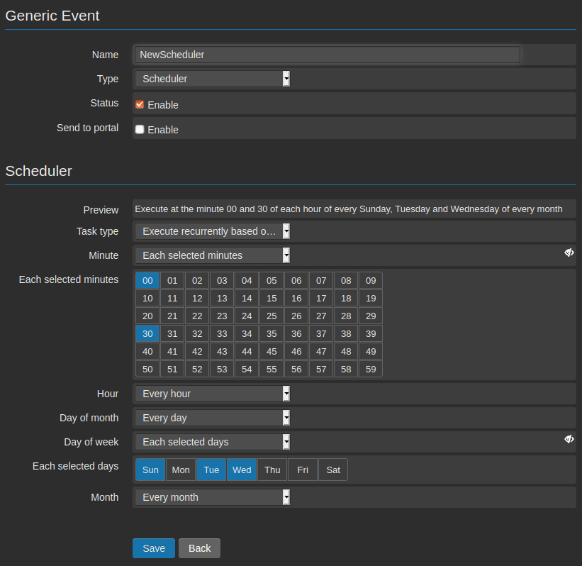
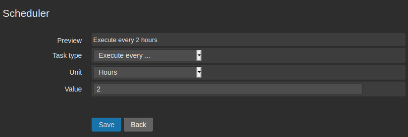
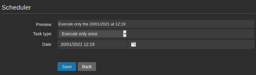
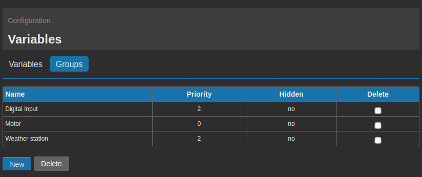
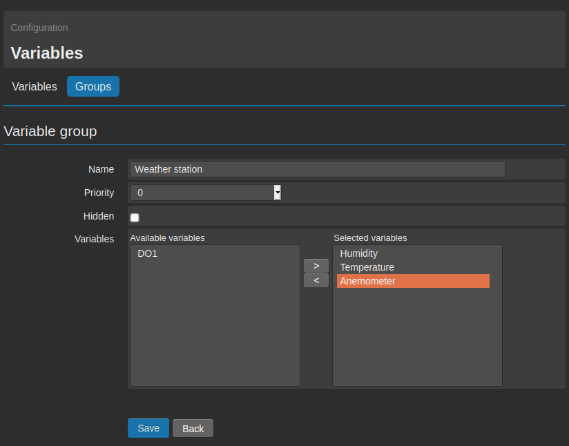
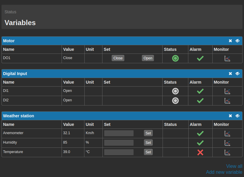
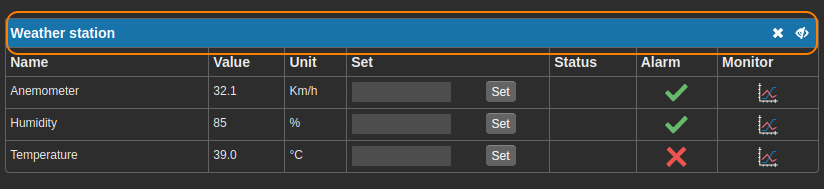
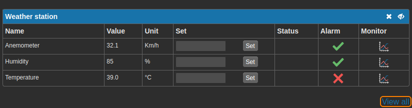
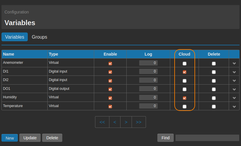
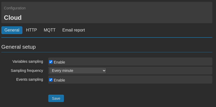
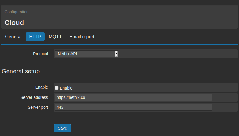
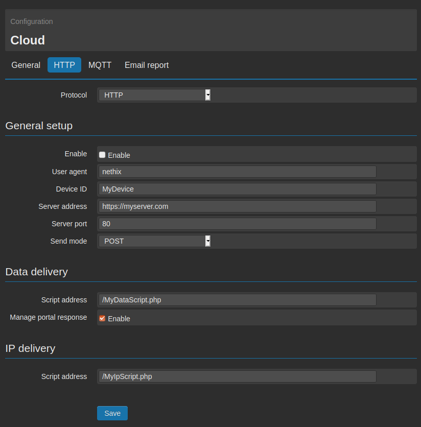
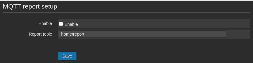
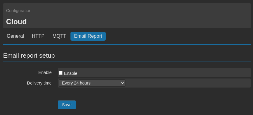
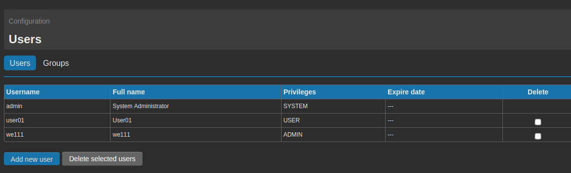
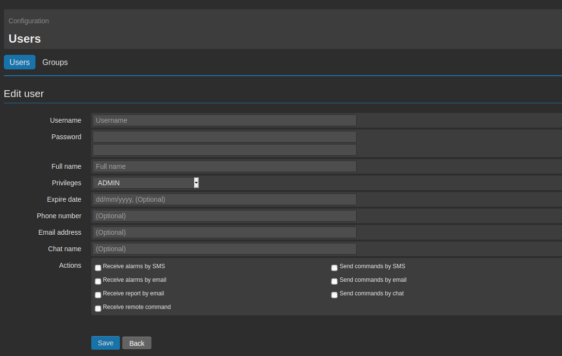
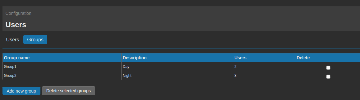
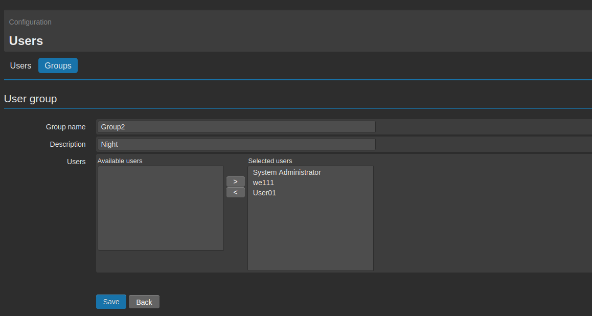
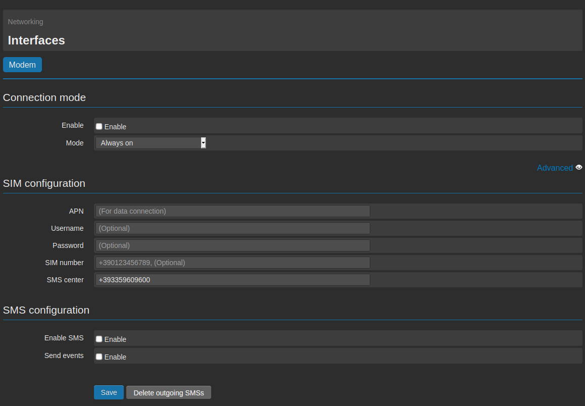
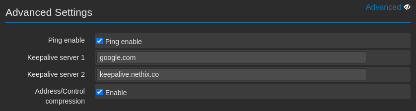
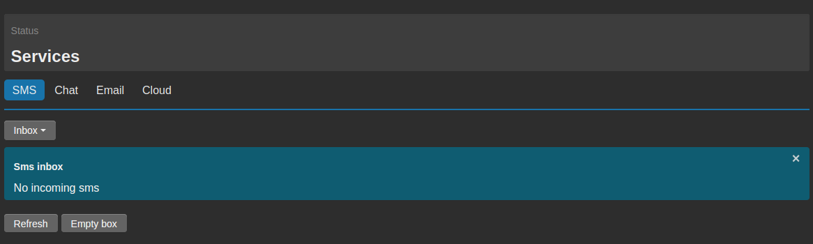
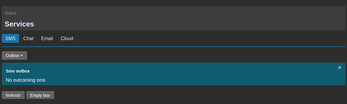
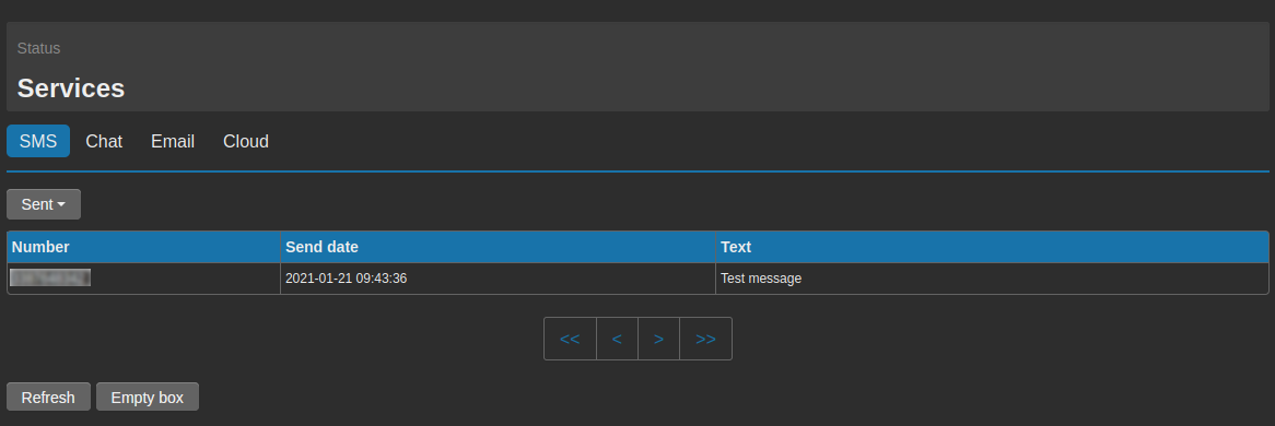
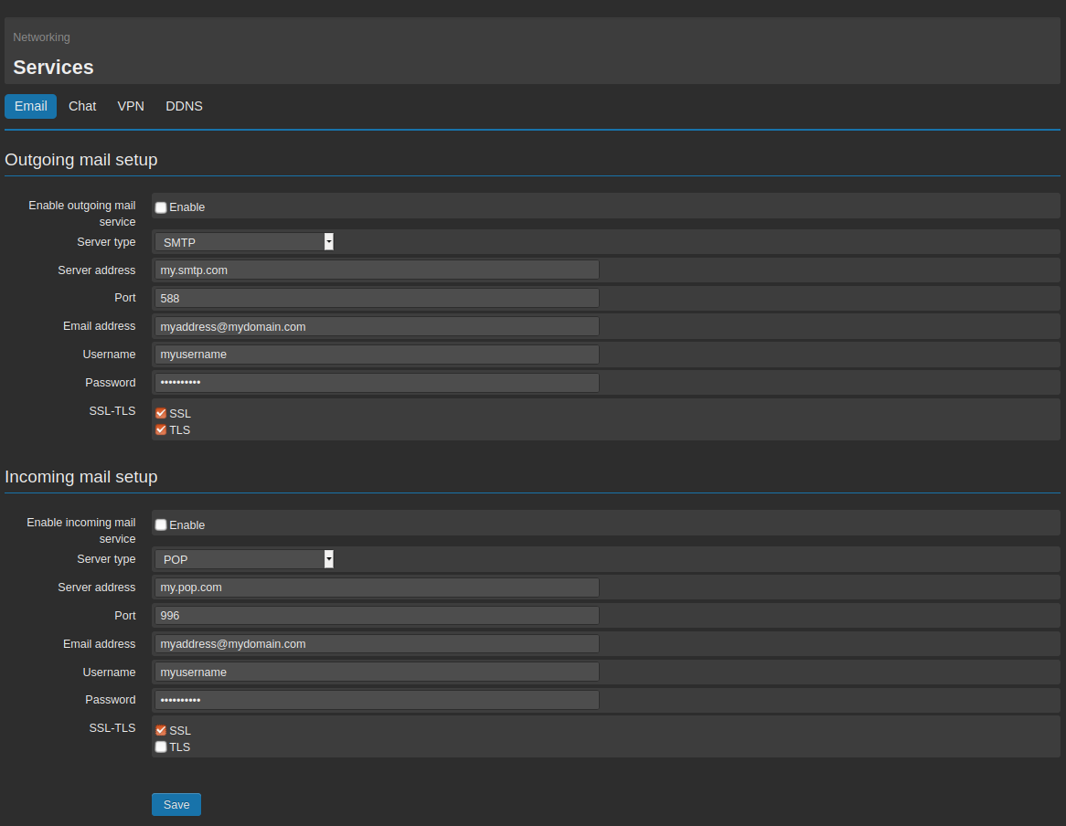
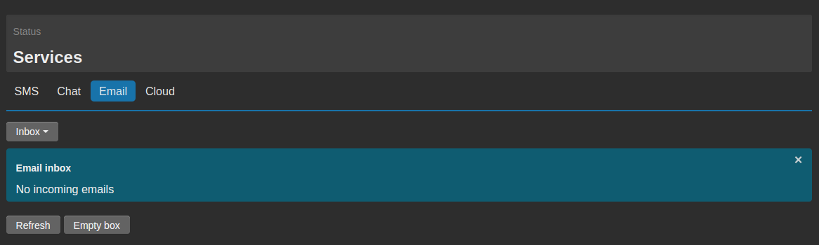
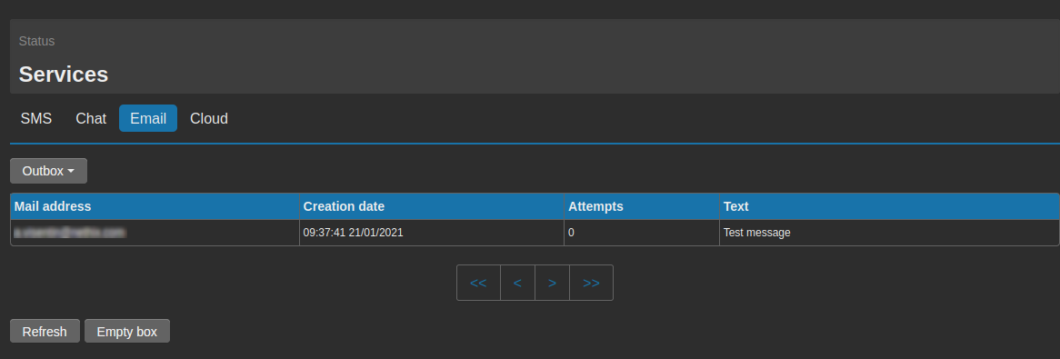
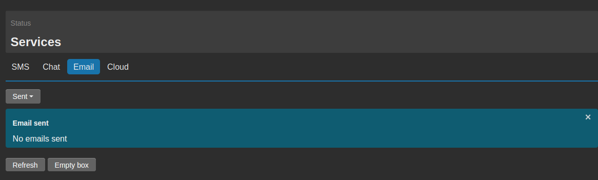
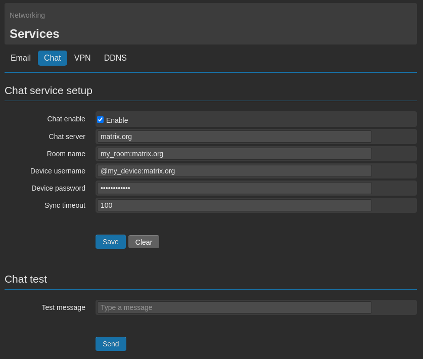
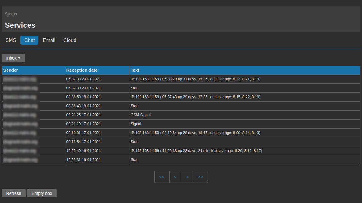

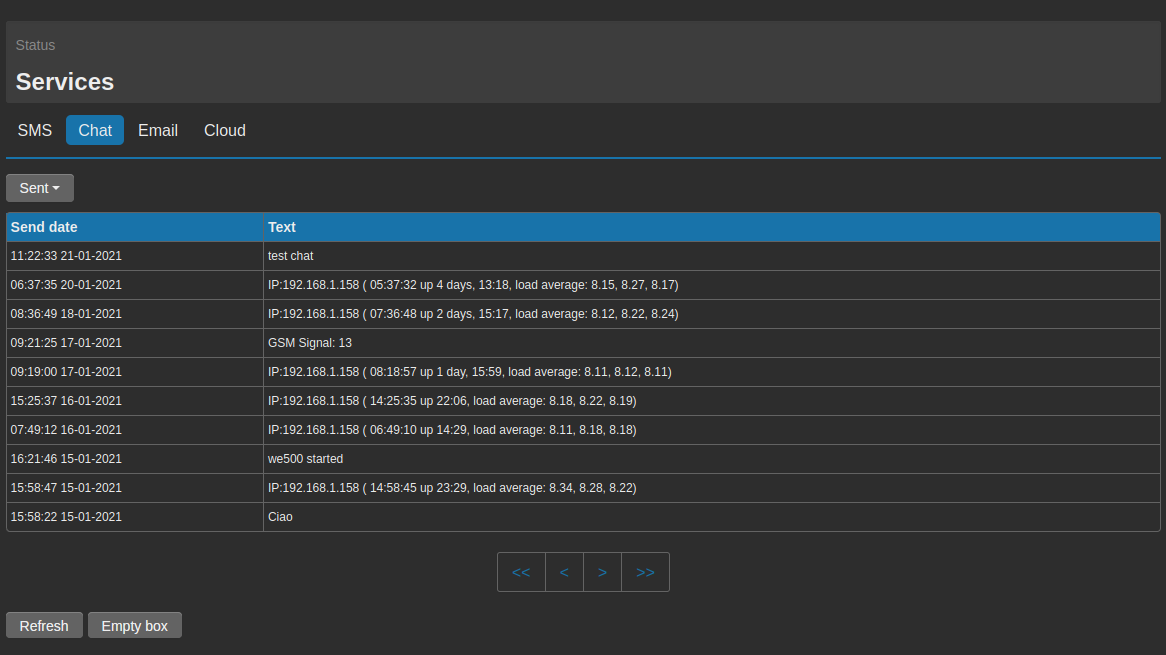
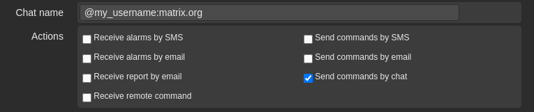
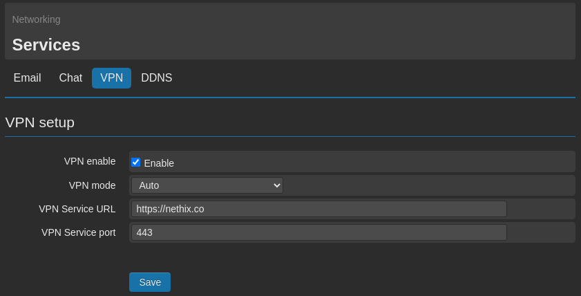
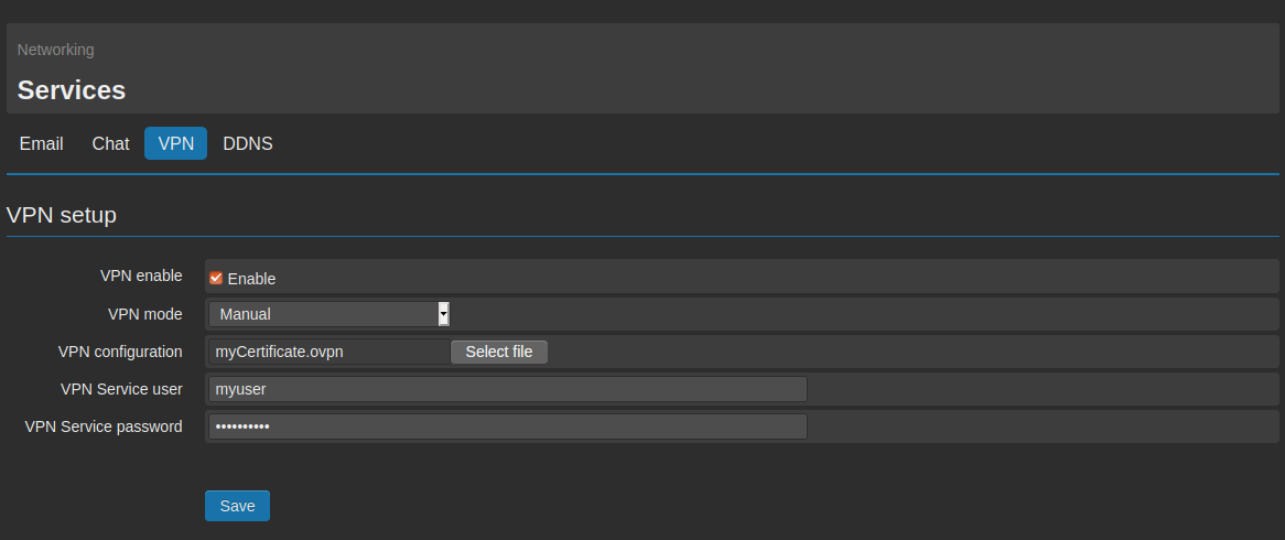
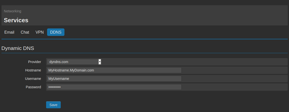
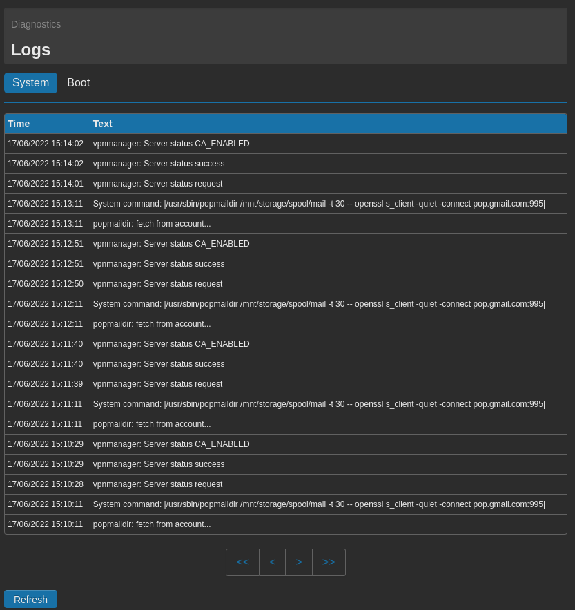
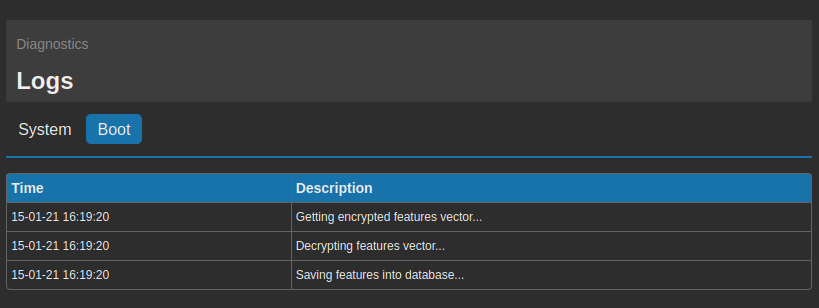
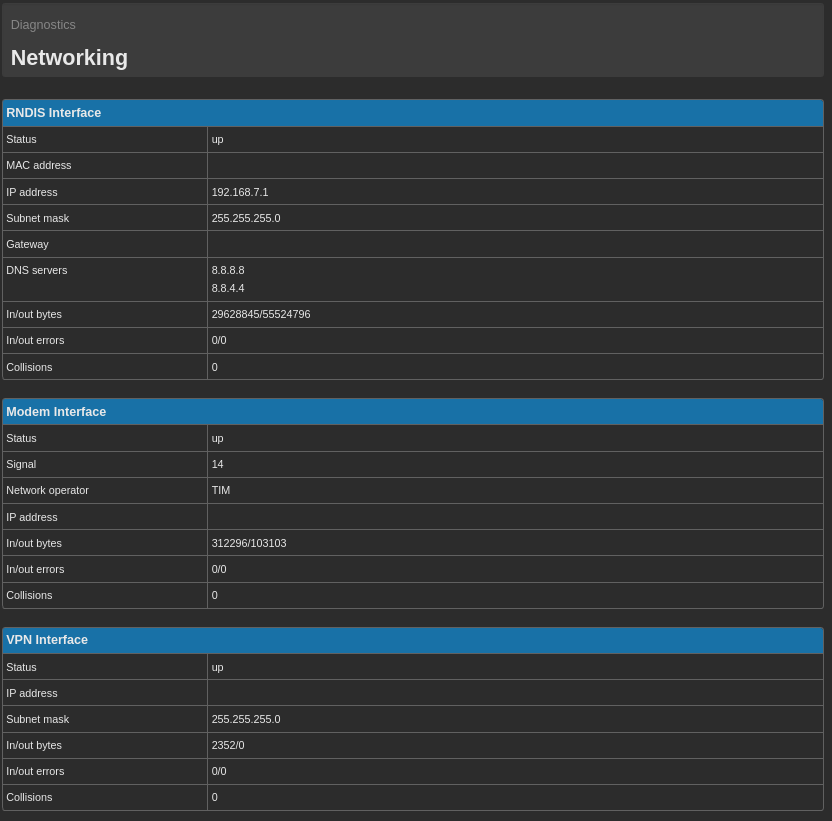
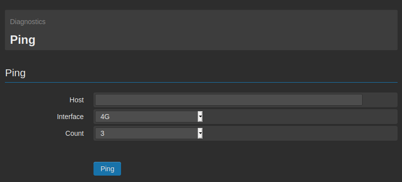
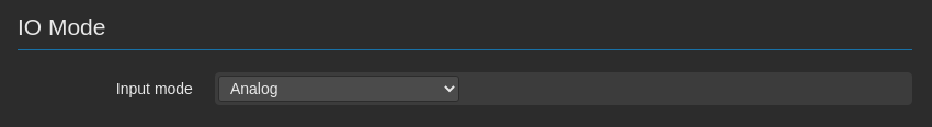
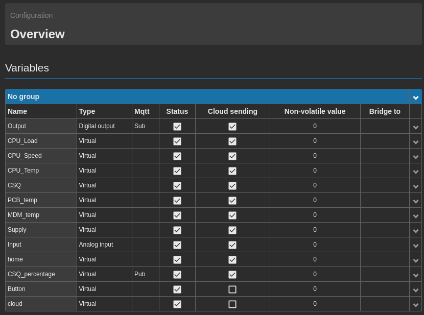
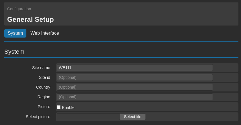
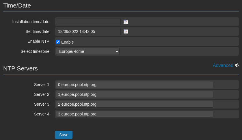
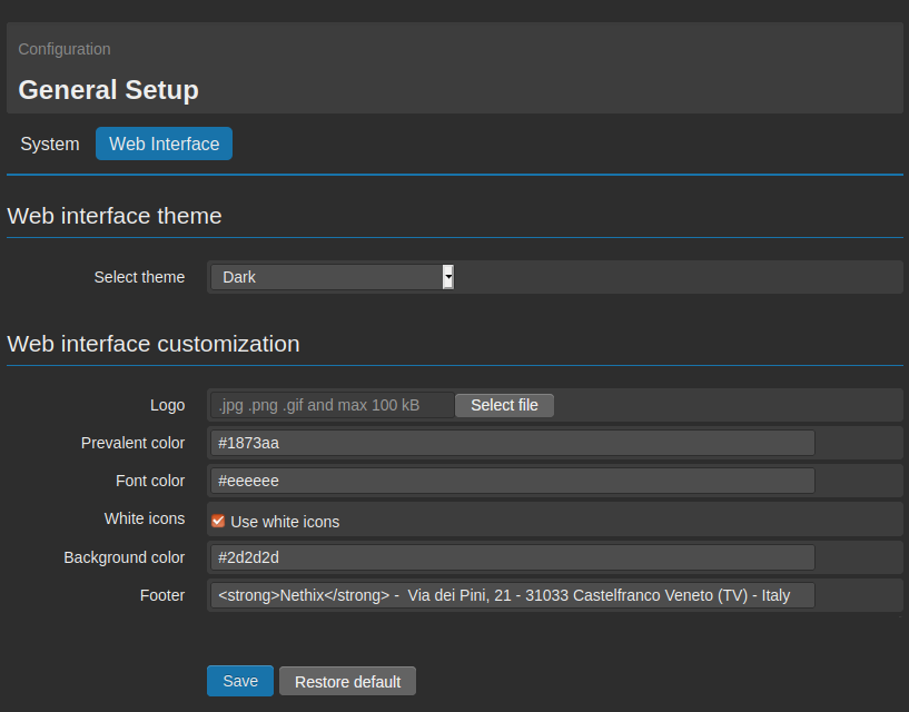
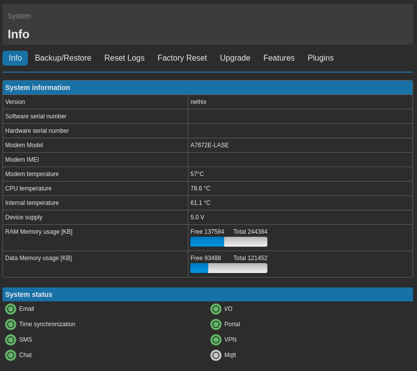
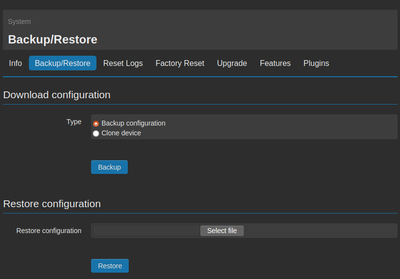
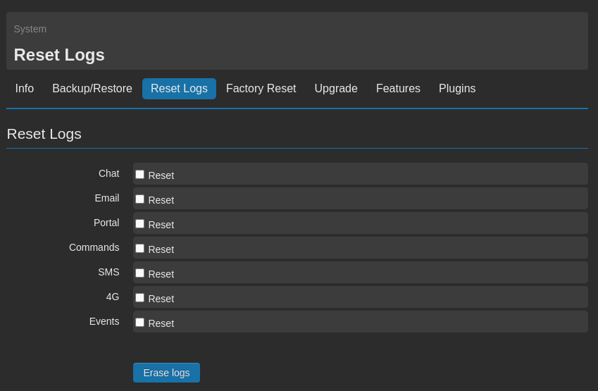
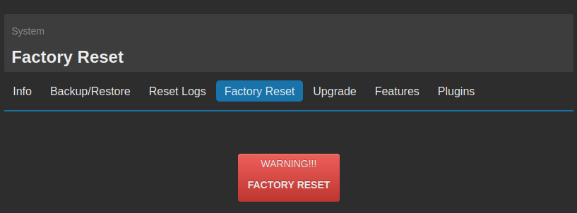
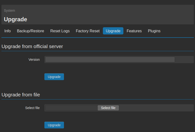
 The product shall not be treated as household waste. It shall be instead handed over to an appropriate collection point for the recycling of electrical and electronic products. For further information about recycling of this product, contact the local city office and/or the local waste disposal service.