- Home
-
Docs
- DeepLog
- App manual
- DeepLog Portal
- Hardware manual
- Portal
- WE110
- Manual for thermostat and generic control
- Manual for gate opener
- Application notes
- Downloads
- WE111
- Web Interface manual
- 1. General information
- 2. Variables management
- 3. Events/Actions
- 4. Scheduler
- 5. Variables monitoring
- 6. Data delivery
- 7. Users
- 8. Connectivity
- 9. System commands
- 10. Diagnostic
- 11. System operations
- 12. Safety guidelines
- 13. Warranty and support
- 14. Return and repair
- Web Interface manual
- WE112
- Web Interface manual
- 1. General information
- 2. Variables management
- 3. Events/Actions
- 4. Scheduler
- 5. Variables monitoring
- 6. Data delivery
- 7. Users
- 8. Connectivity
- 9. System commands
- 10. Diagnostic
- 11. System operations
- 12. Safety guidelines
- 13. Warranty and support
- 14. Return and repair
- Web Interface manual
- WE120
- Quick start guide
- Connecting the WE120 to a computer
- Firmware update
- User manual
- Commands manual
- Genesys 3
- Application notes
- Reference cases
- Downloads
- FAQ
- WE151
- Web Interface manual
- 1. General information
- 2. Variables management
- 3. Modbus
- 4. Events/Actions
- 5. Scheduler
- 6. Variables monitoring
- 7. Data delivery
- 8. Users
- 9. Connectivity
- 10. System commands
- 11. Diagnostic
- 12. System operations
- 13. Safety guidelines
- 14. Warranty and support
- 15. Return and repair
- Web Interface manual
- WE152
- Web Interface manual
- 1. General information
- 2. Variables management
- 3. Modbus
- 4. Events/Actions
- 5. Scheduler
- 6. Variables monitoring
- 7. Data delivery
- 8. Users
- 9. Connectivity
- 10. System commands
- 11. Diagnostic
- 12. System operations
- 13. Safety guidelines
- 14. Warranty and support
- 15. Return and repair
- Web Interface manual
- WE200
- Quick start guide
- Software Manual
- Hardware manual
- Application notes
- QuickTunnel
- Downloads
- WE300
- Quick start guide
- Hardware manual
- Software manual
- 1. General information
- 2. Variables
- 3. Modbus
- 4. Events/Actions
- 5. Scheduler
- 6. Variables monitoring
- 7. Data sending
- 8. Datalogger
- 9. Users
- 10. Settings
- 11. Commands
- 12. Diagnostic
- 13. System operation
- 14. Safety guidelines
- 15. Warranty and support
- 16. Return and repair
- WE500
- Quick start guide
- Hardware manual
- Software Manual
- 1. General information
- 2. Variables
- 3. Modbus
- 4. Events/Actions
- 5. Scheduler
- 6. Variables monitoring
- 7. Data sending
- 8. Datalogger
- 9. Users
- 10. Connectivity
- 11. Commands
- 12. Diagnostic
- 13. System operation
- 14. Safety guidelines
- 15. Warranty and support
- 16. Return and repair
- Plugins
- Application notes
- Reference cases
- API
- FAQ
- WE500R
- Quick start guide
- Hardware manual
- Software Manual
- 1. General information
- 2. Variables
- 3. Modbus
- 4. Events/Actions
- 5. Scheduler
- 6. Variables monitoring
- 7. Data sending
- 8. Datalogger
- 9. Users
- 10. Settings
- 11. Commands
- 12. Diagnostic
- 13. System operation
- 14. Safety guidelines
- 15. Warranty and support
- 16. Return and repair
- API
- VPN
- Touch Panels
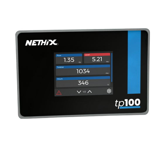
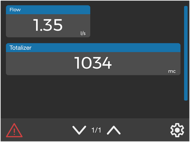
- TP100
- Power supplies
- Expansions
- XP100
- XP500
- XP500/ETH
- DIS500
- DeepLog
- Languages