1. Overview
The WE500 can manage several master and/or slave modbus networks of different kind at the same time.
The present guide shows, through a simple example, how to manage two modbus network at the same time with a single WE500.
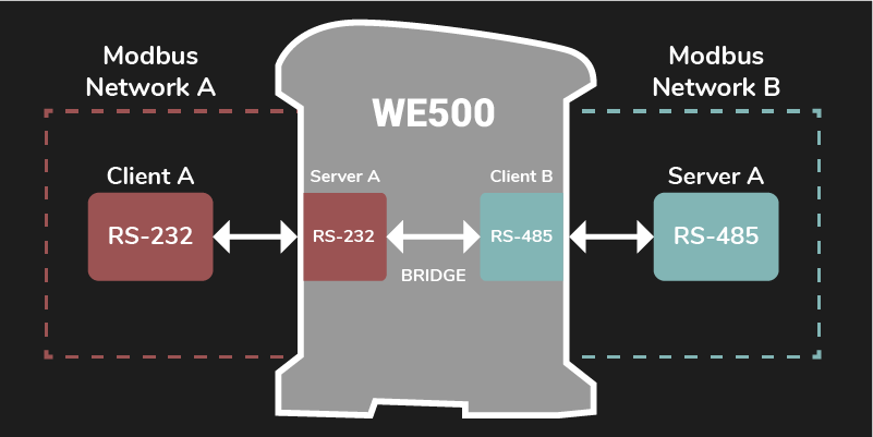
Assume that a device called Master A, that uses the serial interface RS-485, must read several variables from another device called Slave B that uses the serial interface RS-232.
The WE500 is located between these two modbus devices. From the Master A side it’s configured as a slave in the RS-485 interface, whilst from the Slave B it’s configured as a master in the RS-232 interface.
The WE500 configuration must have two modbus networks with their respective commands and variables. An important part of the configuration is the bridge that must be set in order to copy the values from the Slave B variables to the Master A variables.
Note
This guide is useful for quickly learning a specific functionality of the WE500.
Notice that this document does not cover all the functionalities of the WE500. Please refer to the software and hardware manuals for in-depth explanations and a deeper understanding of the WE500.
3. RS-485 serial port configuration
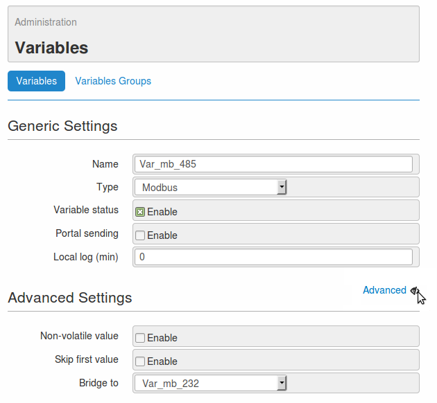
3.1 Modbus variable
Setting up the variable of the RS-485 serial port for the device “B”
Got to the page Administration -> Variables.
Click on the button New to create a new variable.
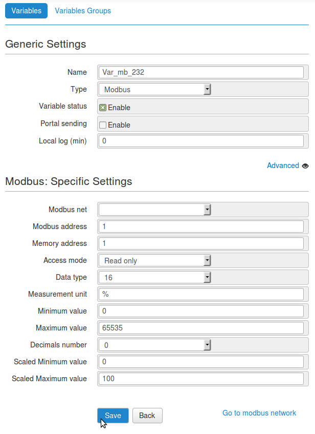
Set up the variable as ndicated below.
- Name: Var_mb_485
- Type: Modbus
- Variable status: enabled
Using the button Advanced available on the right side of the page, open the section Advanced settings.
Set up the bridge as indicated below.
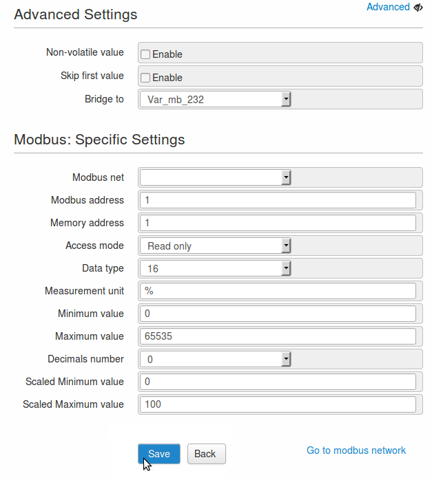
- The configuration procedure continues as follows.
- Modbus net: do not associate with any networks
- Modbus address: 1
- Memory address: 1
- Access mode: Read only
- Data type: 16
- Measurement unit: %
- Minimum value: 0
- Maximum value: 65535
- Decimals number: 0
- Scaled minimum value: 0
- Scaled maximum value: 100
- Save the configuration with the button Save.
Note
The values entered in the set-up above are used only for illustrative purposes.
Using 16 bit it is possible to obtain 65535 as maximum value in decimal base.
In order to let the variable work properly it is necessary to set it up, according to the devices connected to the WE500.
The just created bridge assign to the variable Var_mb_232 the same value collected from the variable Var_mb_485.
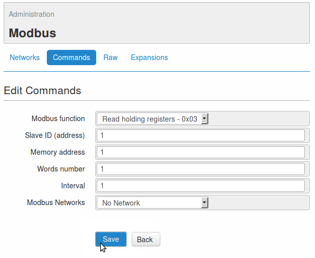
3.2 Modbus command
Setting up the modbus commands of the variable Var_mb_485
- Go to the page Administration -> Modbus -> Commands.
- Create a new command clicking the button Add new command.
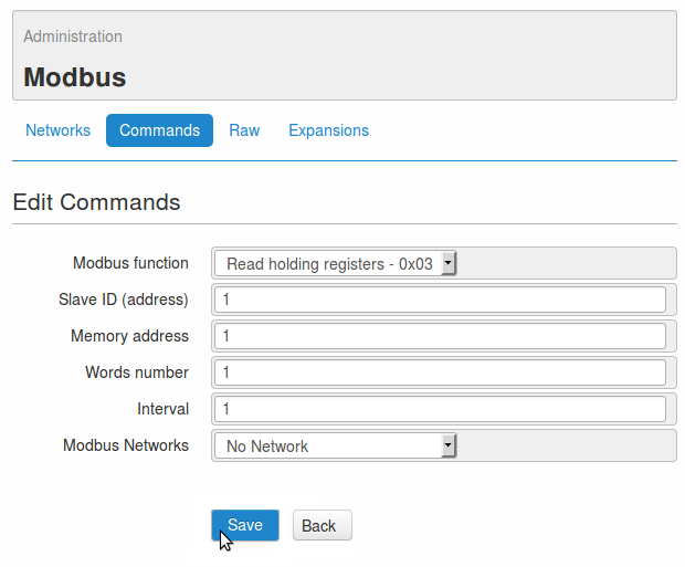
- Set up the fields as below. (or Fill in the fields as indicated below)
- Modbus function: Read holding registers - 0x03
- Slave ID (address): 1
- Memory address: 1
- Words number: 1
- Interval: 1
- Modbus network: do not associate with any networks
- Save the configuration using the button Save.
Note
The values entered in the set-up above are used only for illustrative purposes.
In order to let the command work properly it is necessary to set it up, according to the variable just created.
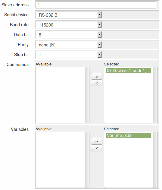
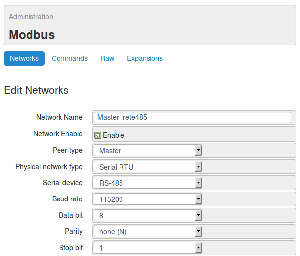
3.3 Modbus network
Setting up the modbus network on the serial port 485 of WE500
- Go to the page Administration -> Modbus -> Networks.
- Click on the button Add new network to create a new netwotk.
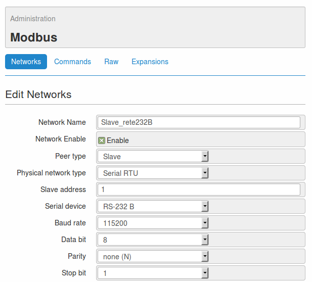
- Fill in the fields as indicated below.
- Network name: Master_rete485
- Network enable: enabled
- Peer type: Master
- Physical network type: Serial RTU
- Serial device: RS-485
- Baud rate: 115200
- Data bit: 8
- Parity: none (N)
- Stop bit: 1
- In the section Commands, select the command 0x03(master:1-addr:1) and link it to the network trough the button >.
- In the section Variables, link the variable Var_mb_485 to the network using the button >.
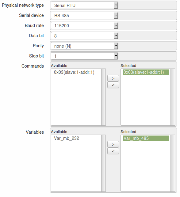
- Save the configuration clicking on the button Save.
Note
The values entered in the set-up above are used only for illustrative purposes.
In order to let the network work properly it is necessary to set it up, according to the devices connected to the WE500.
In this case, the device B must have the modbus network configured as Slave.
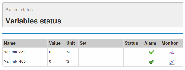
At this stage the WE500 allows the communication betweeen the device “A” and the device “B”, as described on chapter 1. Overview of present document.
At the page Status -> Variables status is possible to display the values of the variables just created.
4. Other examples of modbus network configurations
These are further examples that show different WE500 modbus network architectures:
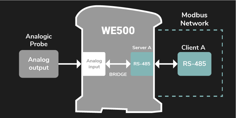
This diagram shows a configuration that is similar to the one already explained in this application note.
The difference is that, instead of having a modbus device from one side, there is only an analogue sensor connected directly to the WE500 through an analogue input.
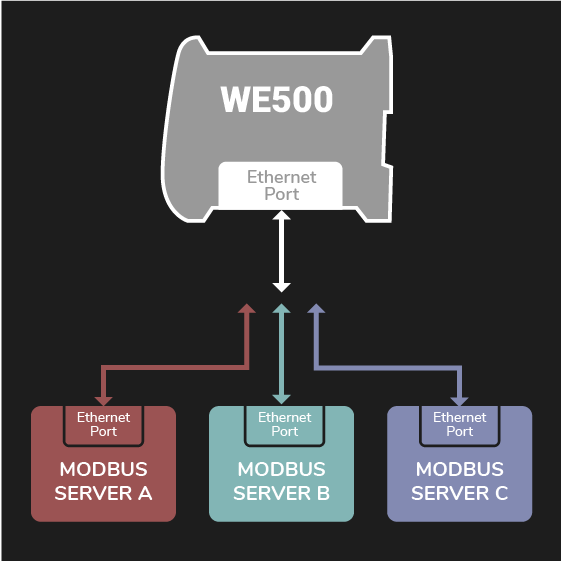
This diagram shows the expandability of the TCP modbus network. In this case there are three modbus networks that communicate to three external devices using the TCP protocol.
This kind of modbus network configuration is described in the application note Modbus master/slave configuration.