XP100
1. Overview
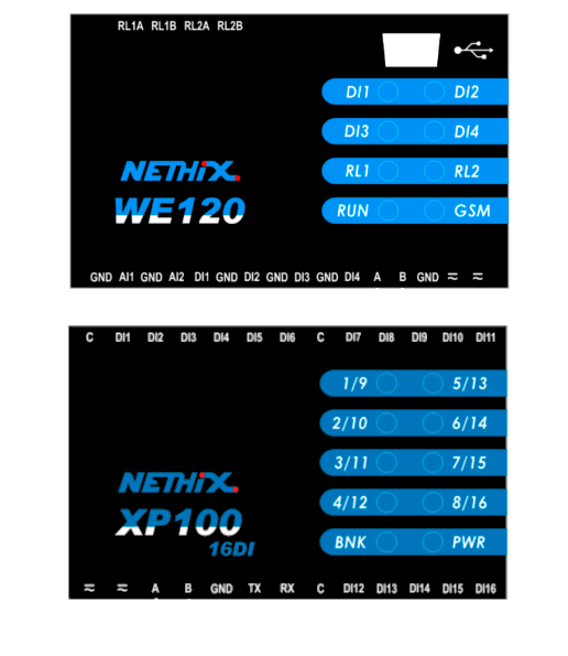
The XP100 product line includes a complete range of smart expansion modules for Nethix remote control devices. They are developed for the integration with Nethix WE120.
The communication between the modules and the host is made through a standard communication protocol, that is Modbus RTU compatible on RS485 multipoint line.
The XP100 devices interface directly with most of the common process signals (tensions, currents, temperatures etc..) and contain the necessary circuits for acquisition, for signal conditioning and for analogue-to-digital conversion.
The XP100-line includes:
- Digital I/O Expansion module with 6-Inputs 6-Outputs: includes 6 PNP/NPN isolated digital inputs and 6 relays outputs
- Digital I/O Expansion with 16-Inputs: includes 16 PNP/NPN isolated digital inputs.
- Analog I/O Expansion with 4-Inputs: includes 4 configurable analog inputs
This document presents all necessary technical information for the installation and the operation of the XP100 expansion modules.
For a proper use of the devices it’s recommended to read carefully the present sheet. The information contained in the present document can be updated at any time without notice.
2. Technical specifications
| Feature |
Description |
|---|
| Power supply |
9-32VDC / 12-24VAC |
| Average consumption |
- 20 mA @ 24VDC
- 50 mA @ 10VDC
|
| Peak consumption |
- 100 mA @ 24VDC
- 250 mA @ 10VDC
|
| Dimensions |
90 x 70 x 60 mm. |
| Weight |
Approx. 180 gr. |
| Enclosure |
Plastic box, DIN bar mountable (4 modules) |
| Storage temperature |
-25° C - +85° C |
| Operating temperature |
-10° C - +70° C |
| Humidity |
5% - 95% (non condensing ) |
| Communication |
Two-wire RS-485 |
| Protocol |
Modbus RTU (slave) |
| Communication
parameters |
9600 Baud, 1 start bit, 8 data bits, 1 stop bit,
no parity |
| Safety |
Transients suppression on RS485 line |
| Line termination |
120 Ohm, configurable through DIP switch |
| Numero massimo nodi |
Up to 32 in multipoint configuration |
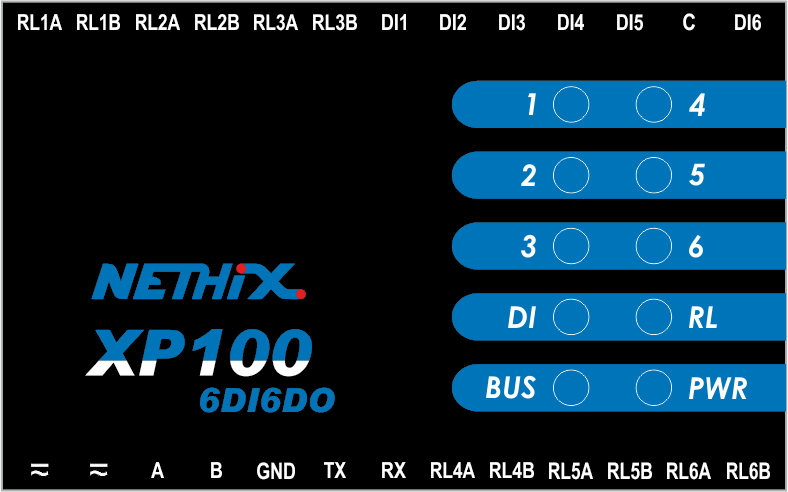
3. XP100 6DI - 6DO
3.1 Technical specifications
- 6 opto-isolated digital 24VDC inputs with universal logic PNP/NPN
- 6 relays 1A/125V outputs
| Inputs |
|---|
| Numbers of channels |
6 |
| Isolation |
2500V max |
| Response time |
~1 ms |
| Nominal voltage |
24V |
| V input min H |
5V |
| V input min L |
2V |
| Input imp. |
~5K |
| Outputs |
|---|
| Number of channels |
6 N.O. relays |
| AC 1 A @ 125V |
| DC 1 A @ 24V |
| Isolation |
500V |
| Response time |
~10 ms |

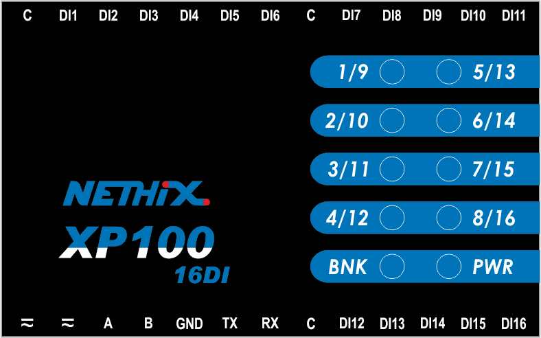
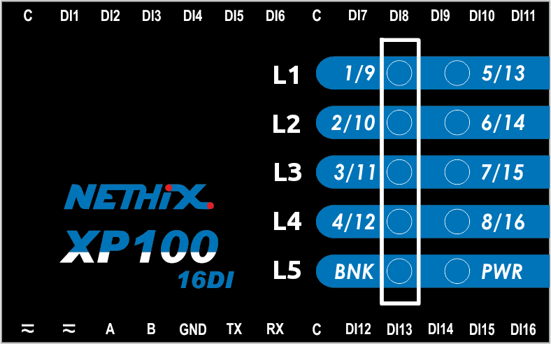
4. XP100 16DI
4.1 Technical specifications
- 16 opto-isolated 24 VDC digital inputs with universal logic PNP/NPN
| Inputs |
|---|
| Number of channels |
16 |
| Isolation |
2500V max |
| Response time |
~1 ms |
| Nominal voltage |
24V |
| V input min H |
5V |
| V input min L |
2V |
| Input imp. |
~5K |

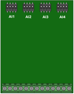
5. XP100 4AI - 4T

5.1 Technical charateristics
- 4 analog inputs setting up in 5 different modes:
- 0-5 V
- 0-10 V
- 0-20 mA
- NTC
- PT100
| Inputs |
|---|
| Channel number |
4 |
| Input type |
V o mA |
| Range input |
0-5 V |
| 0-10 V |
| 0-20 mA |
| Max voltage |
10 V |
| Replay timeout |
100 ms normally |
| Resolution |
10 bit |
| Input impedance |
~1 MOhm (0-5V) |
| ~10 kOhm (0-10V) |
| 250 Ohm (0-20 mA |

| Inputs |
|---|
| Channel number |
4 |
| Input type |
Temperature |
| Range input |
PT100 |
| NTC (10 KOhm @ 25°) |
| Temperature range |
min: -20° max: 80° |
| Replay timeout |
100 ms |
| Resolution |
10 bit |

6. Installation
6.1. Connection
6.2. Setting the slave address
Before use, all devices must be configured and identified on the network through a unique slave address.
For the configuration of the address of an XP100 expansion module, follow the procedure described below:
- Lift the upper panel of the device using a screwdriver, in order to reach the electronic board.
- Power the device and wait a few seconds until the end of the initialization procedure.
- Push briefly the small button on the left.
- The display shows the current slave address of the device, represented by the lighting of the leds 1-5 in binary code. The PWR led blinks slowly.
- Press and hold the configuration button for a few seconds. The PWR led starts to blink fast.
- Each time you press the configuration button, the address is increased by a unit. Repeat this operation until you reach the desired address.
- Finally press and hold the button, in order to save the selected address.

In order to change the address assigned to the device, it’s allowed to repeat the above mentioned procedure at any time.
Warning
The slave addresses assigned to all the XP100 expansion modules connected to the same R485 network must be unique. It’s not possible to assign the same address to more than one device.
6.3 DIP switch
On the upper container of all XP100 modules is available a DIP-SWITCH with 4 different positions, that allows to change the hardware configuration of the device.
Position 1
RESERVED: to be left on ON positions
Position 2-3
Baudrate configuration on serial ports RS232 and RS485:
OFF-OFF: 9600 bps
OFF-ON: 19200 bps
ON-OFF: 38400 bps
ON-ON: 115200 bps
Position 4
Activation of RS485 line termination:
ON: RS485 terminated on 120 Ohm
OFF: RS485 not terminated
6.4 LEDs meaning
XP100 6DI - 6DO
Generic status LED:
- PWR (power) – indicates that the devices is on and properly initialized
- BUS (status)- when blinking, inidcates that the Modbus/RS485 communication is in progress.
Inputs/Outputs status LED:
- DI- on, it indicates that the leds 1-6 show the status of the digital inputs
- RL- on, it indicates that the leds 1-6 show the status of the relays outputs
XP100 16DI
Generic status LED
- PWR (power) – indicates that the devices is on and properly initialized
Inputs/Outputs status Led
- BNK LED:
- On, it indicates that the leds 1/9-8/16 show the status of the DI1-D18 digital inputs.
- Off, it indicates that the leds show the status of the DI9-DI16 digital inputs
Warning
The simultaneous blinking of all the leds indicates a malfunction of the device: in this case please contact Nethix Technical Support.
XP100 4AI - 4T
Generic status LED
- PWR (power) – indicates that the devices is on and properly initialized
- BUS (status)- when blinking, inidcates that the Modbus/RS485 communication is in progress
Warning
The simultaneous blinking of all the leds indicates a malfunction of the device: in this case please contact Nethix Technical Support.
7. Warnings
- This device is only suitable for being installed by a qualified operator
- Nethix is not responsible for improper use and/or its side effects
- Nethix products are designed for typical use in industrial automation and/or home applications.
If you plan to use Nethix products in special applications where anomalies and discontinuity of service can have serious effect on human life or can cause physical or material damages, or where extremely high levels of reliability are required (for example in aerospace systems, in atomic energy control systems or n electro-medical devices), please contact Nethix for support to your particular application. Nethix is not responsible of damages caused from its products if such applications are not previously authorized.
 The product shall not be treated as household waste. It shall be instead handed over to an appropriate collection point for the recycling of electrical and electronic products. For further information about recycling of this product, contact the local city office and/or the local waste disposal service.
8. Warranty and support
Nethix warrants to the buyer that the product will be defect-free within two years (24 months) from the date of purchase.
During warranty time, and against presentation of purchase invoice, the product will be repaired or replaced, at Nethix’s discretion, without any additional costs as regards spare parts and repair, if the damages are proven to be manufacturing defects.
Warranty will be voided if the product has not been used properly.
In case of technical problems the user can ask for support:
9. Return and repair
Product return to NETHIX must be previously authorized, requesting a RMA number.
Please send an Email at Nethix containing all following information:
- Complete customer’s name and address
- Distributor’s or Reseller’s name and address
- Date of purchase
- Product P/N and S/N as displayed on the product or the package
- Detailed description of fault and/or reason for return
Nethix will communicate the RMA number, in order to start the return procedure of the product.
The delivery of the goods shall be arranged DDP at Nethix premises.
Products returned without factory seals will be automatically treated as out-of-warranty repair services.